Photo-control receptacle

a technology of photocontrol receptacles and receptacle bodies, which is applied in the field of electrical technology, can solve the problems of complex assembly process and waste of time and labor, poor contact with electrical contacts, and complex forming process of receptacle bodies, and achieves the effect of convenient operation

Active Publication Date: 2016-04-21
QICHENG ELECTRICAL EQUIP
View PDF3 Cites 12 Cited by
  • Summary
  • Abstract
  • Description
  • Claims
  • Application Information

AI Technical Summary

Benefits of technology

[0031](8) In the photo-control receptacle of the invention, a grab ring assembly is arranged and when installing, the contact surface contacts with the housing of the lamp to press the elastic arms of the clasps. The photo-control receptacle can be fixed in the housing of the lamp by the pushing force of the elastic arm and the elastic force applied by the grabbing pieces of the grab ring assembly grabbing the mounting base, due to the fact that the housing of the lamp is fixed, so as to achieve the tool-free installation, i.e. installation without use of tools. In addition, the fixin

Problems solved by technology

However, a screwdriver and other tools are used to install the existing photo-control receptacles, which leads to a complex assembly process and wastes time and labor.
However, after inserting the metal pin, the electrical contact of the photo-control receptacle applies a push force on the metal pin towards outside of the mounting hole because of the rear side mounting, and the metal pin will separate from the mounting position after inserting and removing multiple times, which leads to a poor contac

Method used


Image

  • Photo-control receptacle
  • Photo-control receptacle
  • Photo-control receptacle

Examples


embodiment 1

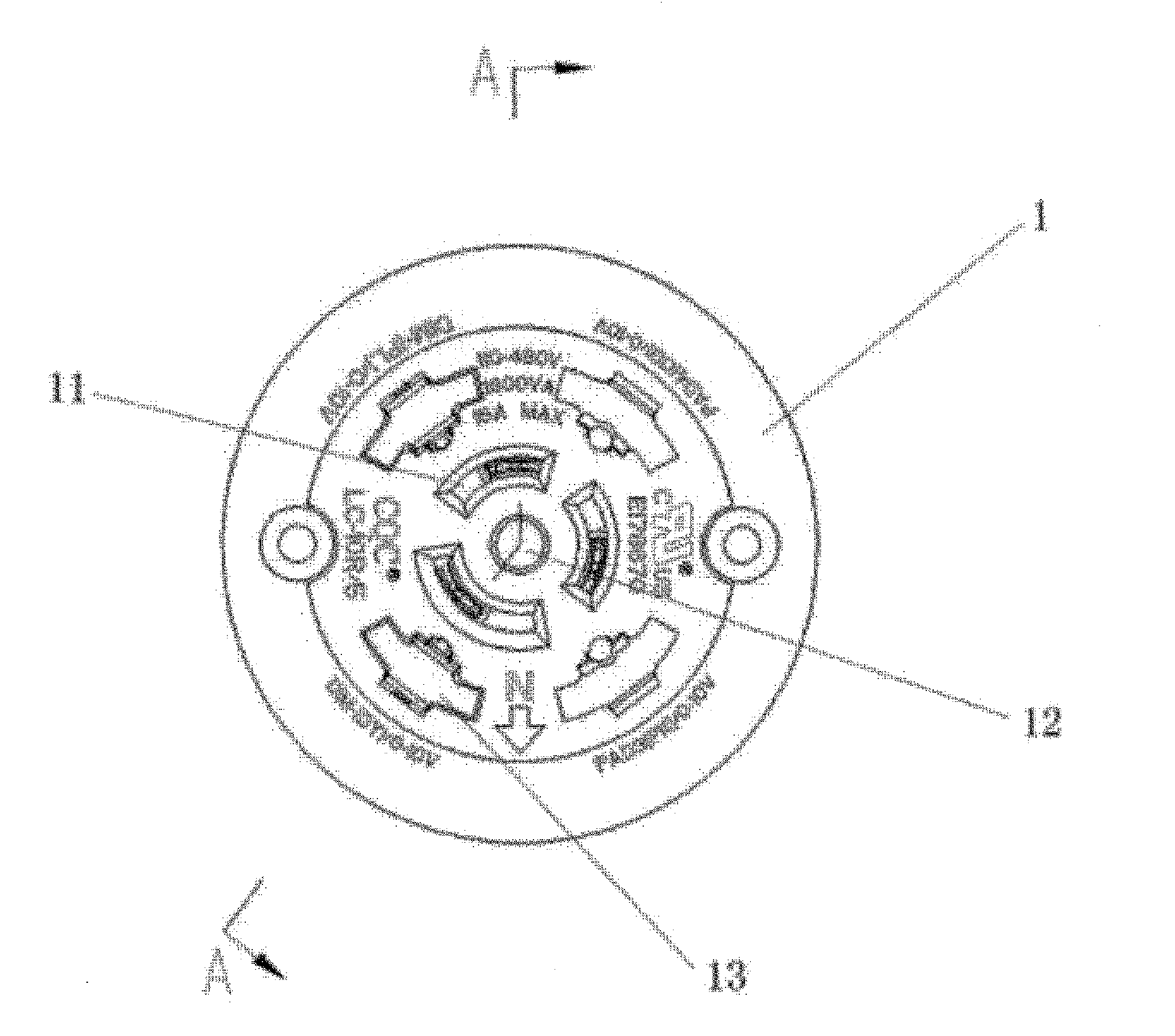
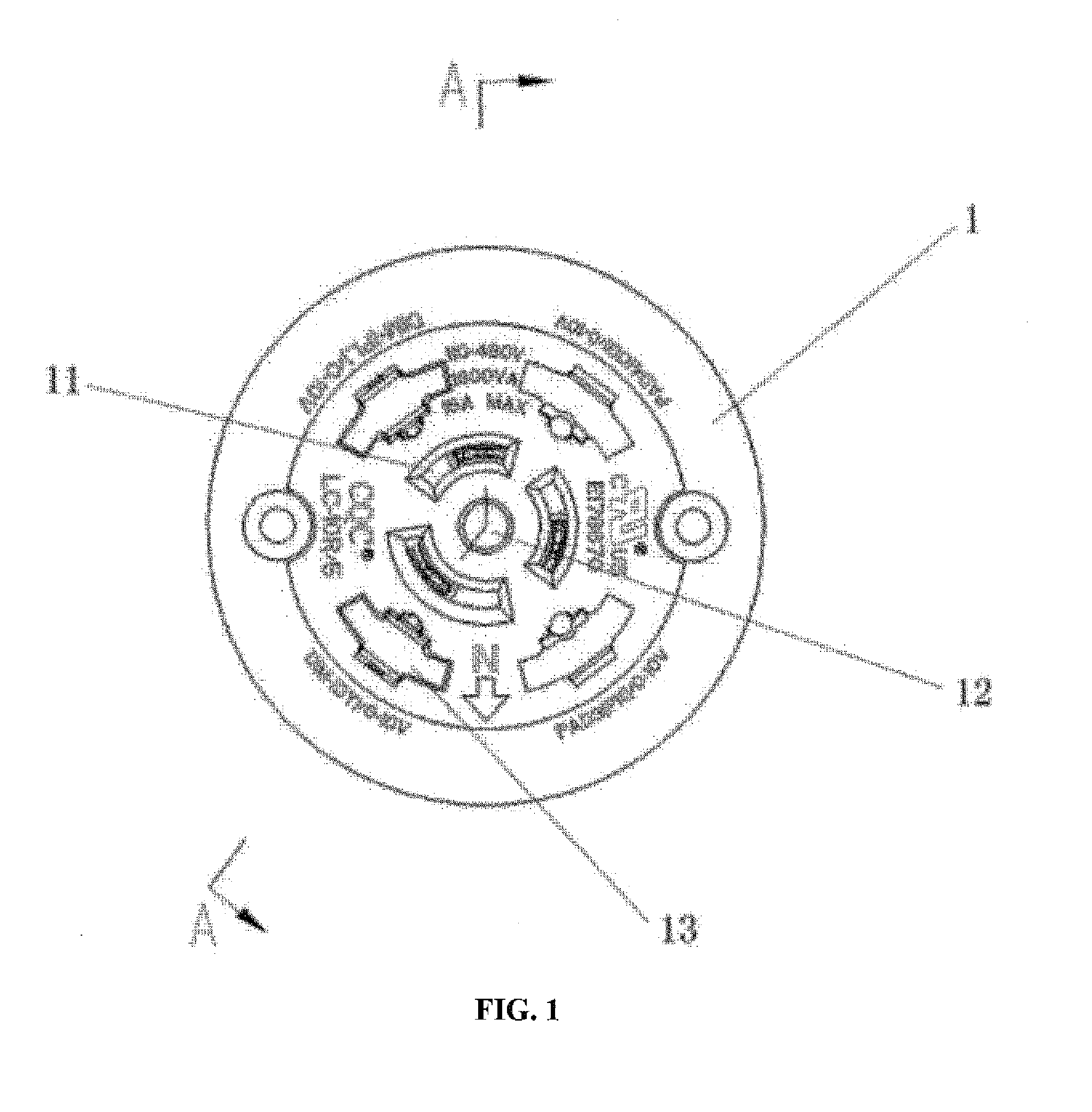
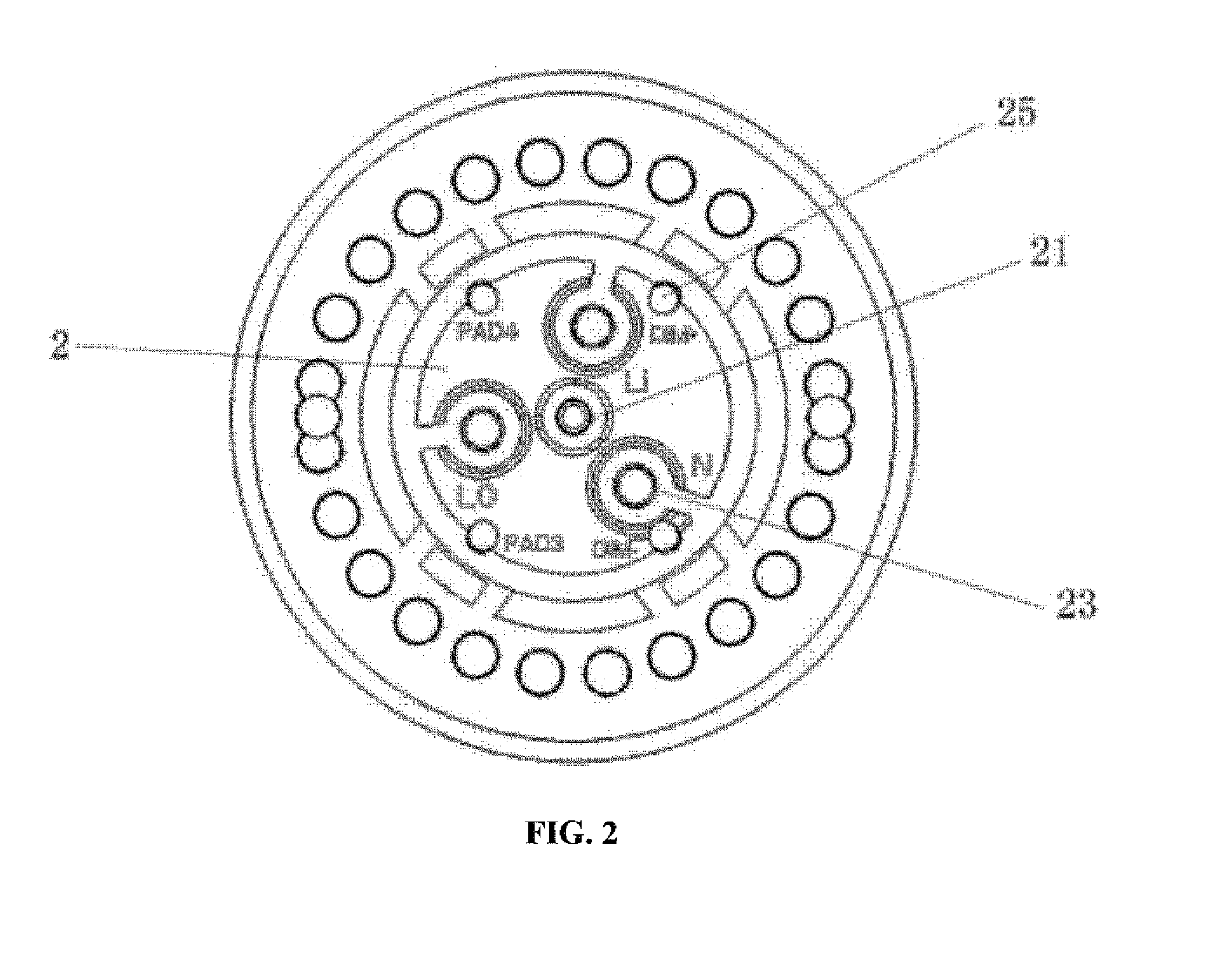
[0045]One embodiment of a photo-control receptacle is illustrated in FIG. 1-5 and comprises a base 1, having a power jack 11 formed on one side and a pin holding groove 14 formed on the other side thereof and communicated with the power jack 11; a mounting base 2, connected with the base 1 through a connecting structure, having a plurality of pin mounting grooves 22 arranged on one end and a cable groove 23 arranged on the other end thereof and communicated with the pin mounting grooves 22; wherein, each of the pin mounting grooves 14 has a metal pin 3 arranged therein, which is further arranged to extend into the pin holding groove 14, the cable groove 23 has a cable arranged therein and connected with the metal pin 3.

[0046]The photo-control receptacle embodiment is divided into two relatively independent structures by connecting the base 1 and the mounting base 2 formed separately with a connecting structure, so as to simplify the forming process and reduce the cost of the mold ma...

embodiment 2

[0055]A photo-control receptacle provided in embodiment 2 has further improvement on the embodiment 1, the differences therebetween are that a plurality of function jacks 13 are formed on one side of the base 1, each of the function jacks has a metal piece 4 arranged therein as shown in FIG. 1, and the mounting base 2 has a plurality of cable through holes 25 arranged thereon, which allows cables to extend therethrough and be inserted into the base 1 to connect with the metal pieces (4) electrically as shown in FIG. 2.

[0056]Special needs to be pointed out that not all of the function jacks 13 are arranged with metal pieces 4, one or more metal pieces 4 can be arranged into the function jacks 13 as needed, for example, four function jacks are shown in FIG. 1, two of which have two metal pieces 4 arranged therein while the other two do not have, or all the four function jacks 13 have a metal piece arranged therein.

[0057]The photo-control receptacle of embodiment 2 as shown in FIGS. 6 ...

embodiment 3

[0068]The photo-control receptacle of embodiment 3 is an improvement of embodiment 1 or 2, the differences with embodiment 1 or 2 are: a circular slot 26 and a grab ring assembly 6 are formed on the side wall of the mounting base 2, and the elastic grab ring assembly 6 comprises a grab ring 60, a plurality of clasps 62 disposed on one side of the grab ring close to the mounting base 2 and a plurality of grabbing pieces 61 disposed on the grab ring 60, arranged in the circular slot 26 and grabbing therein, so as to fix the elastic grab ring assembly 6 in the circular slot 26.

[0069]In particular, a plurality of grabbing pieces 61 can be arranged on the two sides of the grab ring 60 or only one side thereof, but making sure the grab ring assembly 6 cannot move with the elastic force applied by the clasps 62.

[0070]The photo-control receptacle of embodiment 3, each clasp 62 is provided with an arm 622 with one end being pendent, and a contact surface formed on the top of the pendent end....


PUM


Abstract

The invention relates to a photo-control receptacle, which comprises a base, having a power jack formed on one side and a pin holding groove formed on the other side thereof and communicated with the power jack; a mounting base, connected with the base through a connecting structure, having a plurality of pin mounting grooves arranged on one end and cable grooves arranged on the other end thereof and communicated with the pin mounting grooves; wherein, each of the pin mounting grooves has a metal pin arranged therein, which is further arranged to extend into the pin holding groove, the cable groove has a cable arranged therein and connected with the metal pin. The photo-control receptacle of the utility model achieves the tool-free installation, the assembly process is simple and saves time and labor. In addition, according to the actual situation, the orientation of the photo-control device can be adjusted by changing the relative position of the base and the mounting base.

Description

CROSS-REFERENCE TO RELATED APPLICATIONS[0001]Pursuant to 35 U.S.C. §119 and the Paris Convention Treaty, this application is a national stage application based on Chinese Patent Application No. 201420607161.2 filed on Oct. 20, 2014. This application claims the priority of this prior application and incorporates its disclosures by reference in its entireties.BACKGROUND OF INVENTION[0002]1. Field of the invention[0003]The utility model relates to a photo-control receptacle and belongs to the field of electrical technology.[0004]2. Description of the Related Art[0005]A photo-control device is a control device used to control light switches by sensing the change of light and widely employed in controlling street and yard lighting. In order to work effectively, it is necessary to consider the corresponding light source or position of the environment when the photo-control device is installed. Mostly, a photo-control receptacle is used to cooperate with and power the photo-control device ...

Claims


Application Information

Patent Timeline
IPC IPC(8): H01R13/533
CPCH01R13/533H01R4/184H01R13/111H05B47/11Y02B20/40H01R2103/00H01R24/78H01R25/003H01J9/00
Inventor YE, XUANFENG
Owner QICHENG ELECTRICAL EQUIP
Why Eureka
Try Eureka