Supercharge Your Innovation With Domain-Expert AI Agents!

Stator Comprising a Split Core and Method for Producing Such a Stator

a stator and split core technology, applied in the direction of dynamo-electric machines, electrical apparatus, magnetic circuit shapes/forms/construction, etc., can solve the problems of motor braking force, appearance of torque, increase in cost, size and mass, etc., and achieve the effect of easy adjustment of motor

Active Publication Date: 2016-04-21
SAFRAN ELECTRONICS & DEFENSE
View PDF7 Cites 2 Cited by
  • Summary
  • Abstract
  • Description
  • Claims
  • Application Information

AI Technical Summary

Benefits of technology

The invention aims to provide a way to easily adjust the motor to a maximum short-circuit torque when it is manufactured. The decoupling teeth help reduce magnetic coupling between the poles, which improves the motor's performance.

Problems solved by technology

Furthermore, some breakdowns of the motor or of its control electronics may lead the motor to exert a braking force.
In particular, when the faulty motor has a short-circuit between phases, the driving of the element by the other motor causes the rotation of the rotor of the faulty motor, inducing in the short-circuited phases a current that cannot be discharged and causes the appearance of a torque.
The motors must therefore be able to produce a higher torque, which increases their cost, size and mass.
This also increases the losses by Joule effect, degrading the performance of the motor and making cooling of the motor necessary.

Method used


Image

  • Stator Comprising a Split Core and Method for Producing Such a Stator
  • Stator Comprising a Split Core and Method for Producing Such a Stator
  • Stator Comprising a Split Core and Method for Producing Such a Stator

Examples


Embodiment Construction

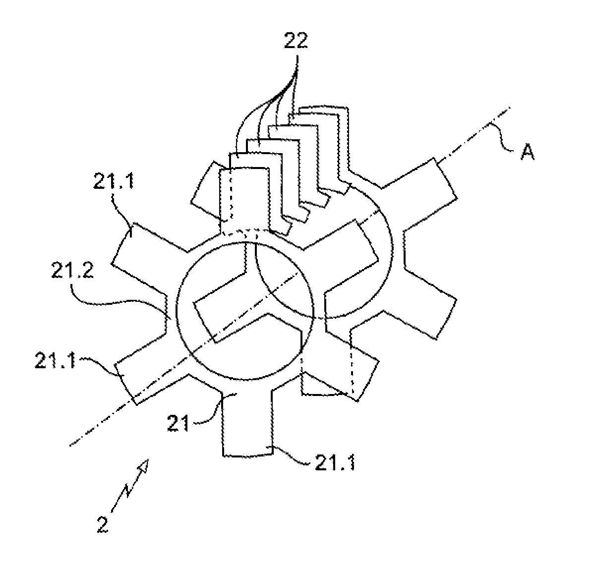
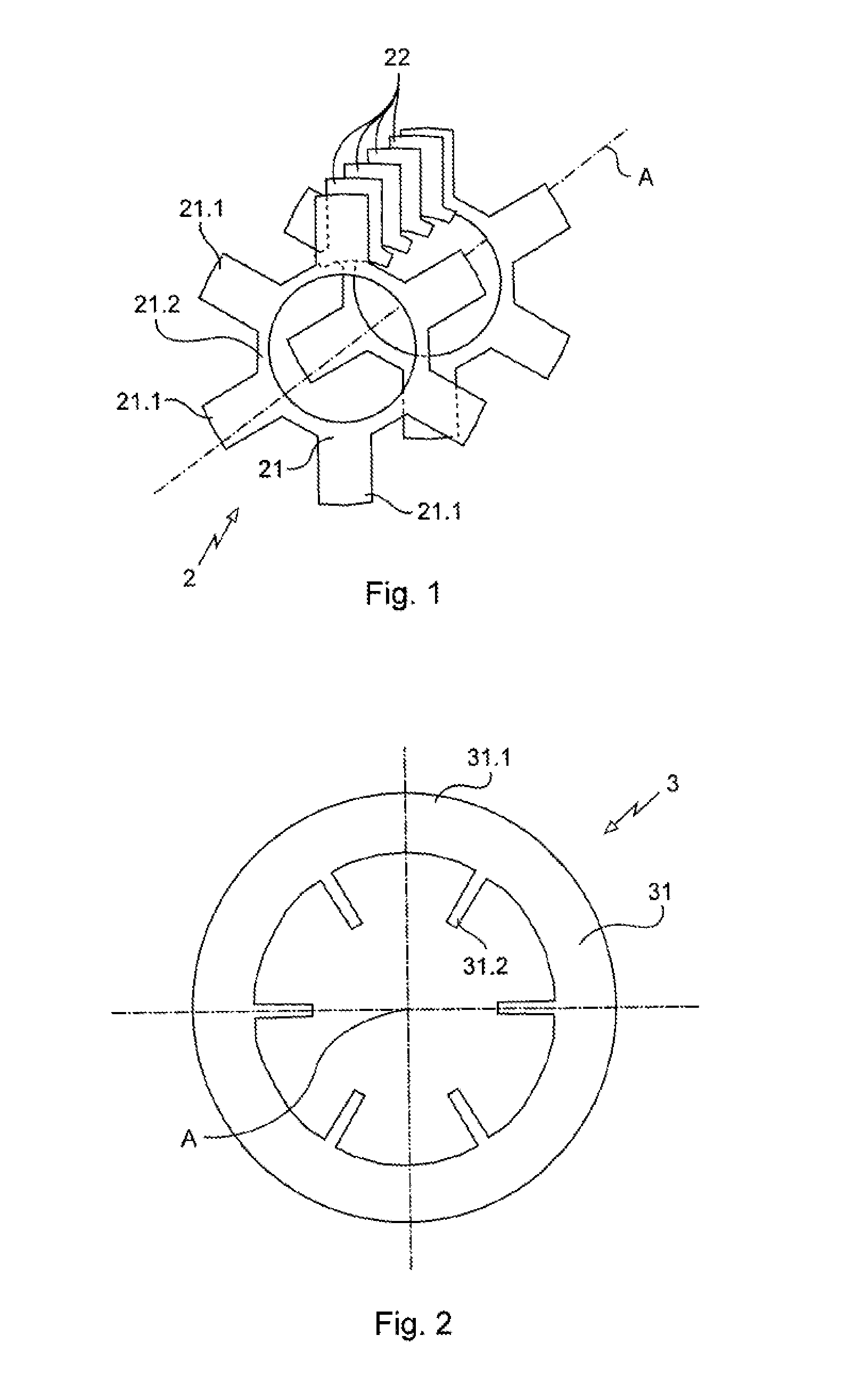
[0027]With reference to FIGS. 1 to 4, the electric motor comprises a stator 1 and a rotor mounted so as to pivot in the stator 1 about an axis A (normal of the plane of FIGS. 2 and 3). The rotor is known per se and, as the invention does not relate to it, it is not shown in the figures and will not be described in further detail hereinafter.

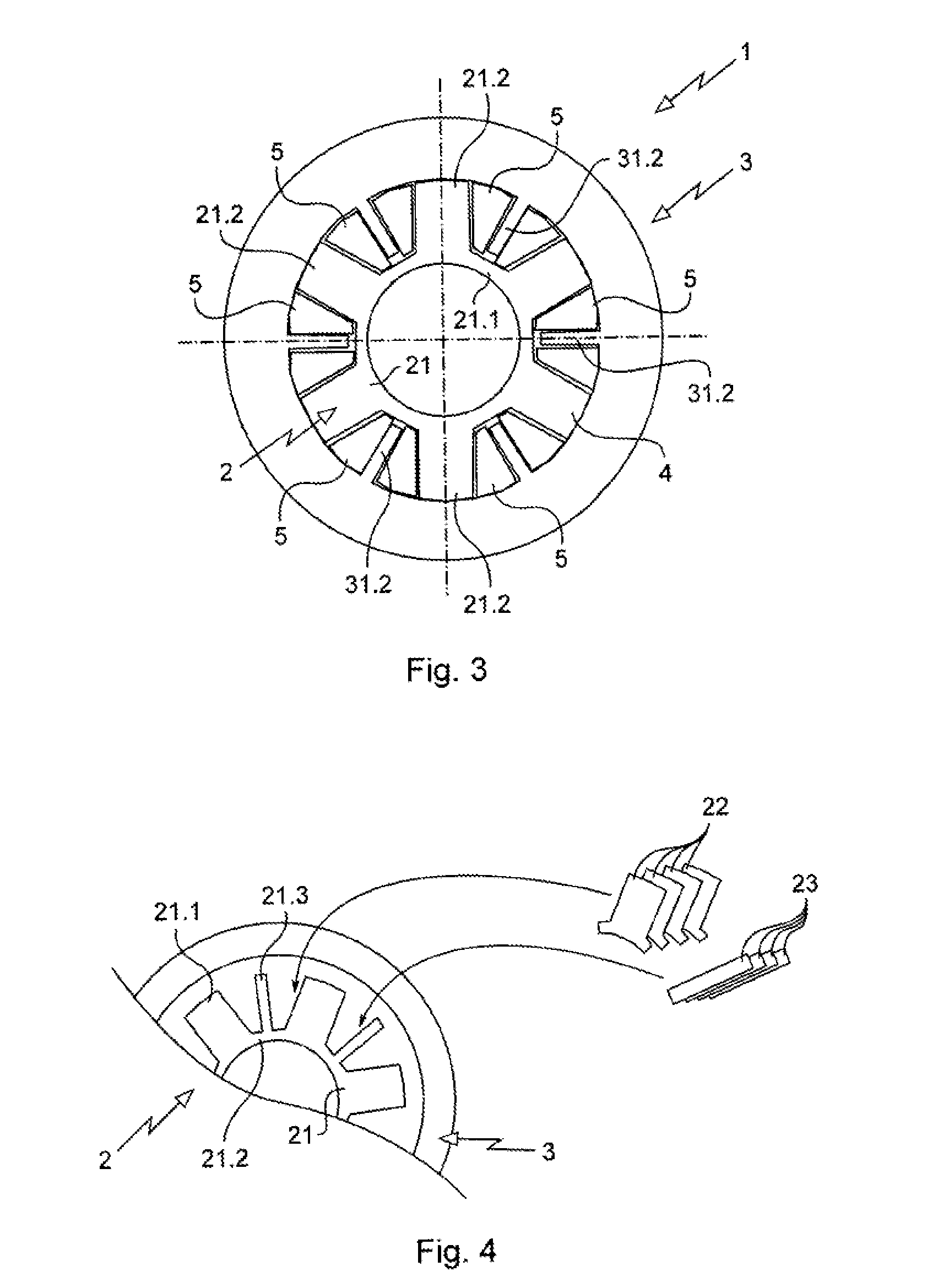
[0028]The stator 1 comprises a central part designated overall as 2, with an annular form defining a housing receiving the rotor pivotally, and a yoke 3 surrounding central part 2.

[0029]The central part 2 comprises a bundle of laminations delimiting poles 4 or teeth. The bundle of laminations comprises a plurality of first laminations 21 and second laminations 22. The laminations are stacked along the axis A.

[0030]Each first lamination 21 comprises portions 21.1 each forming a pole part and an annular internal portion 21.2 that joins the portions 21.1 to one another.

[0031]Each second lamination 22 forms a pole part and is mounted with other secon...


PUM


Abstract

An electric motor stator wherein an annular central part and a yoke surrounding the central part, the central part includes a bundle of laminations delimiting poles, wherein the bundle of laminations includes a plurality of first laminations each containing portions forming a pole part that are joined by an annular internal portion, second laminations each forming a pole part being mounted between the first laminations, the first laminations being spaced apart from one another at a predetermined spacing according to a required inductance.

Description

BACKGROUND OF THE INVENTION[0001]The present invention relates to a stator of an electric motor, the electric motor comprising such a stator and a method for producing such a motor. The invention relates for example to motors with magnets.[0002]Such motors are for example used for moving flight surfaces in an aircraft with electric flight controls.[0003]A motor generally comprises a rotor mounted so as to pivot in a stator formed by a bundle of laminations defining poles surrounded by electric circuits in coils in order to constitute electrical phases for driving the motor.[0004]Some drive devices comprise a first motor and a second motor that are connected to the same movable element in order both to be able to drive this element independently of each other. The rotors of the two motors may for this purpose be connected to the same shaft.[0005]In nominal operating mode, only the first motor is controlled so as to drive the element; the second motor is used only in the event of fail...

Claims


Application Information

Patent Timeline
Patent Type & Authority Applications(United States)
IPC IPC(8): H02K1/14H02K15/02
CPCH02K15/022H02K1/148H02K29/03
Inventor RABRET, BERNARDPIATON, JEROMEBESSEDE, THIERRY
Owner SAFRAN ELECTRONICS & DEFENSE
Features
  • R&D
  • Intellectual Property
  • Life Sciences
  • Materials
  • Tech Scout
  • Unparalleled Data Quality
  • Higher Quality Content
  • 60% Fewer Hallucinations
Learn More