Arrangement of an electromagnet for controlling a central valve

a technology of electromagnet and central valve, which is applied in the direction of electromagnet, valve details, magnetic materials, etc., can solve the problems of thrust pin wear and sliding pairing of the spherical spherical spherical pin, and achieve the effect of stable hydrodynamic lubricating film

Active Publication Date: 2016-04-28
SCHAEFFLER TECH AG & CO KG
View PDF8 Cites 2 Cited by
  • Summary
  • Abstract
  • Description
  • Claims
  • Application Information

AI Technical Summary

Benefits of technology

[0005]It is an object of the present invention to provide an arrangement of an electromagnet for controlling a central valve in such a way that a stable hydrodynamic lubricating film is produced and wear on a contact surface of the sliding partners control piston and thrust pin is greatly minimized or prevented.
[0010]The relative movement, resulting from the installation position, between the contact surface of the control piston and the front face of the thrust pin, i.e., due to the circular path of the thrust pin on the contact surface of the control piston, forms a stable hydrodynamic lubricating film due to the high sliding speed of the thrust pin on the control piston. Friction between the sliding partners, composed of control piston and thrust pin, may be reduced by this stable hydrodynamic lubricating film. As a result, wear on the contact surface of the sliding partners is reduced or prevented.

Problems solved by technology

The low or lacking sliding speed of the sliding partners relative to one another prevents or hinders the buildup of a stable hydrodynamic lubricating film and thus fosters wear on the sliding pairing due to a lack of lubrication and increased friction.
Dry friction thus occurs, whereby in particular the surface roughness of the control piston results in wear of the thrust pin.

Method used


Image

  • Arrangement of an electromagnet for controlling a central valve
  • Arrangement of an electromagnet for controlling a central valve
  • Arrangement of an electromagnet for controlling a central valve

Examples


Embodiment Construction

[0016]Identical reference numerals are used for elements of the present invention which are identical or which act in an identical manner. Furthermore, for the sake of clarity, the individual figures show only reference numerals which are necessary to describe the figure in question. The illustrated specific embodiments are merely examples of how the arrangement according to the present invention of an electromagnet for controlling a central valve may be configured, and thus do not represent any final limitation of the present invention.

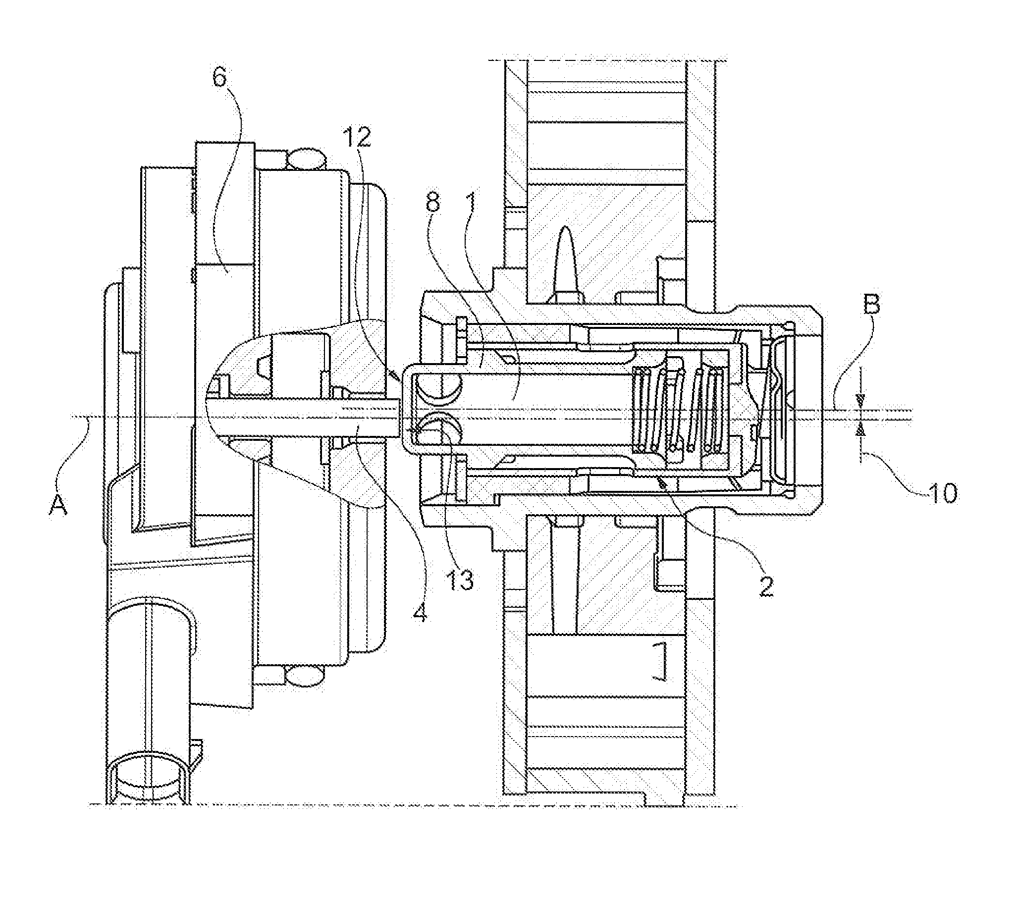
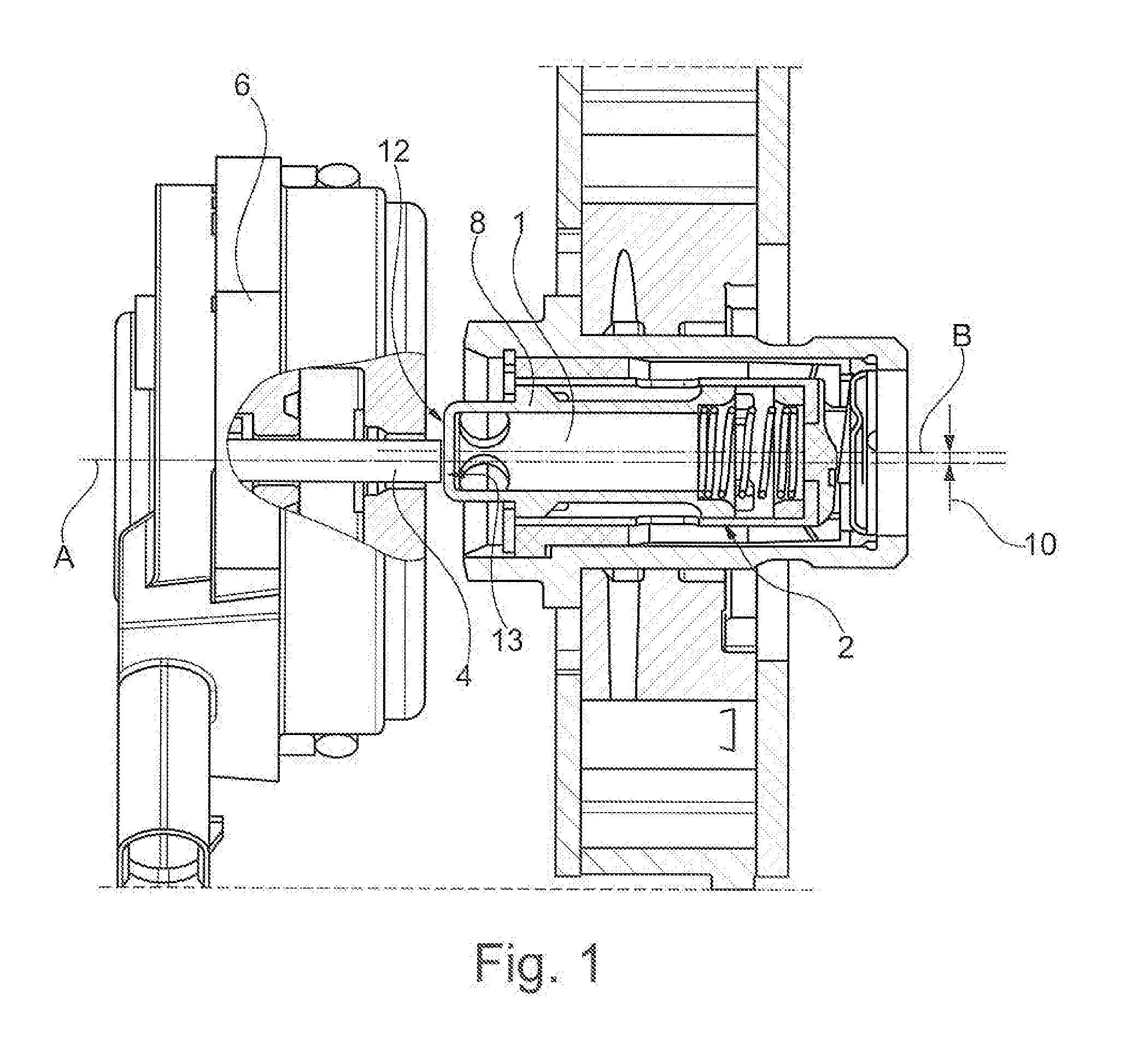
[0017]FIG. 1 shows a longitudinal section of the arrangement according to the present invention of an electromagnet 6 for controlling a central valve 2, in the installed state. Here, a thrust pin 4 is coupled to electromagnet 6 so that thrust pin 4 is movable along a first axis A. Thrust pin 4 acts, in its axial movement, on a control piston 1 of central valve 2. Control piston 1 is displaceable along a second axis B in a central valve housing 8 with...


PUM

PropertyMeasurementUnit
radial distanceaaaaaaaaaa
distanceaaaaaaaaaa
speedsaaaaaaaaaa

Abstract

An arrangement of an electromagnet (6) for controlling a central valve (2) is provided. A thrust pin (4) is coupled to the electromagnet (6) and can be moved along a first axis (A) in such a way that a control piston (1) of the central valve (2) can be displaced along a second axis (B) in a central valve housing (8) by the movable thrust pin (4). The first axis (A) of the thrust pin (4) extends parallel to and at a radial spacing (10) relative to the second axis (B) of the control piston (1).

Description

[0001]The present invention relates to an arrangement of an electromagnet for controlling a central valve. A thrust pin is coupled to the electromagnet and is movable along a first axis in such a way that a control piston of the central valve is displaceable along a second axis in a central valve housing with the aid of the movable thrust pin.BACKGROUND OF THE INVENTION[0002]In internal combustion engines, camshafts are used to actuate the so-called gas exchange valves. The cams of the camshafts usually rest against cam followers. When a camshaft is set in rotation, the cams thus roll against the cam followers, which in turn actuate the gas exchange valves. The angular shift of the camshaft relative to a crankshaft in order to achieve optimized control times for different speeds and load states is referred to as camshaft adjustment. One design variant of a camshaft adjuster operates, for example, according to the known swivel motor principle.[0003]The camshaft adjuster is in this ca...

Claims


Application Information

Patent Timeline
Patent Type & Authority Applications(United States)
IPC IPC(8): F16K31/06H01F7/17
CPCH01F7/17F16K31/0675F01L1/344F01L2001/3443F01L2001/34433
Inventor HOPPE, JENSKINSCHER, MARKUS
Owner SCHAEFFLER TECH AG & CO KG
Why Eureka
Try Eureka