Cleaning system for tube and shell heat exchanger

a technology of cleaning system and heat exchanger, which is applied in the direction of cleaning hollow objects, cleaning brushes, rotary devices, etc., can solve the problems of increasing pressure drop across the board, significantly impairing the performance of heat exchangers, and degrading the performance of shell and tube heat exchangers

Inactive Publication Date: 2016-04-28
KING FAHD UNIVERSITY OF PETROLEUM AND MINERALS
View PDF8 Cites 20 Cited by
  • Summary
  • Abstract
  • Description
  • Claims
  • Application Information

AI Technical Summary

Problems solved by technology

Straight through heat exchangers are typically selected when the tube side fluid deposits materials in the tube or is corrosive because it is usually more difficult to clean the curve in a U-tube type.
The performance of shell and tube heat exchangers degrades over time by the deposition of solids from the tube side flow onto the inside wall of the heat exchanger tubes.
This is commonly referred to as tube side fouling and can significantly impair the performance of heat exchangers.
This fouling can also cause increased pressure drops across the tubes thereby decreasing flow through the tubes.
Under certain conditions, these deposits can also promote corrosion of the inside of the tube wall, a phenomenon known as under-deposit corrosion.
This corrosion, if left unchecked, can produce leak paths through the tube wall allowing commingling of the heat exchange fluid and the process fluid.
Over time, heat exchangers tend to develop residue on the surfaces of the tubes, tube sheets, tube support plates and other internal structural parts.
Over time, this residue can have an adverse affect on the operational performance of the exchangers.
The same problem can arise for all piping and tubing found in industrial facilities.
These deposits are often relatively hard and therefore difficult to remove from the tube walls.
The cost of disassembling and then reassembling the heat exchanger to permit access to the tubes for cleaning and inspection can be significant.
More significant in many situations is the lost production cost from taking the heat exchanger and its associated equipment out of service.
This type of work is extremely labor intensive and potentially hazardous.
Further, those persons in close proximity to the cleaning environment can be exposed to high pressure water, hazardous cleaning chemicals or other potentially toxic, poisonous or volatile materials.
All of these manual methods result in the loss of use of the heat exchanger during cleaning and incur the cost associated with the cleaning itself.
Furthermore, after cleaning and during operation, the tubes begin to foul and continue fouling resulting in a reduction in heat transfer until the next cleaning.
In the case of acid cleaning, pitting and corrosion of the tube may occur.
The costs associated with reduced capacity of heat exchanger tubes can also be substantial in situations where the throughput of process fluids has to be curtailed.
While these on-line systems avoid having to take the heat exchanger out of service, there is significant cost associated with the necessary piping and valving.
Further, these methods are prone to plugging of the tube by debris that has been loosened by the tube cleaners.

Method used


Image

  • Cleaning system for tube and shell heat exchanger
  • Cleaning system for tube and shell heat exchanger
  • Cleaning system for tube and shell heat exchanger

Examples


Embodiment Construction

[0051]Referring now to the drawings, wherein like reference numerals designate identical or corresponding parts throughout the several views.

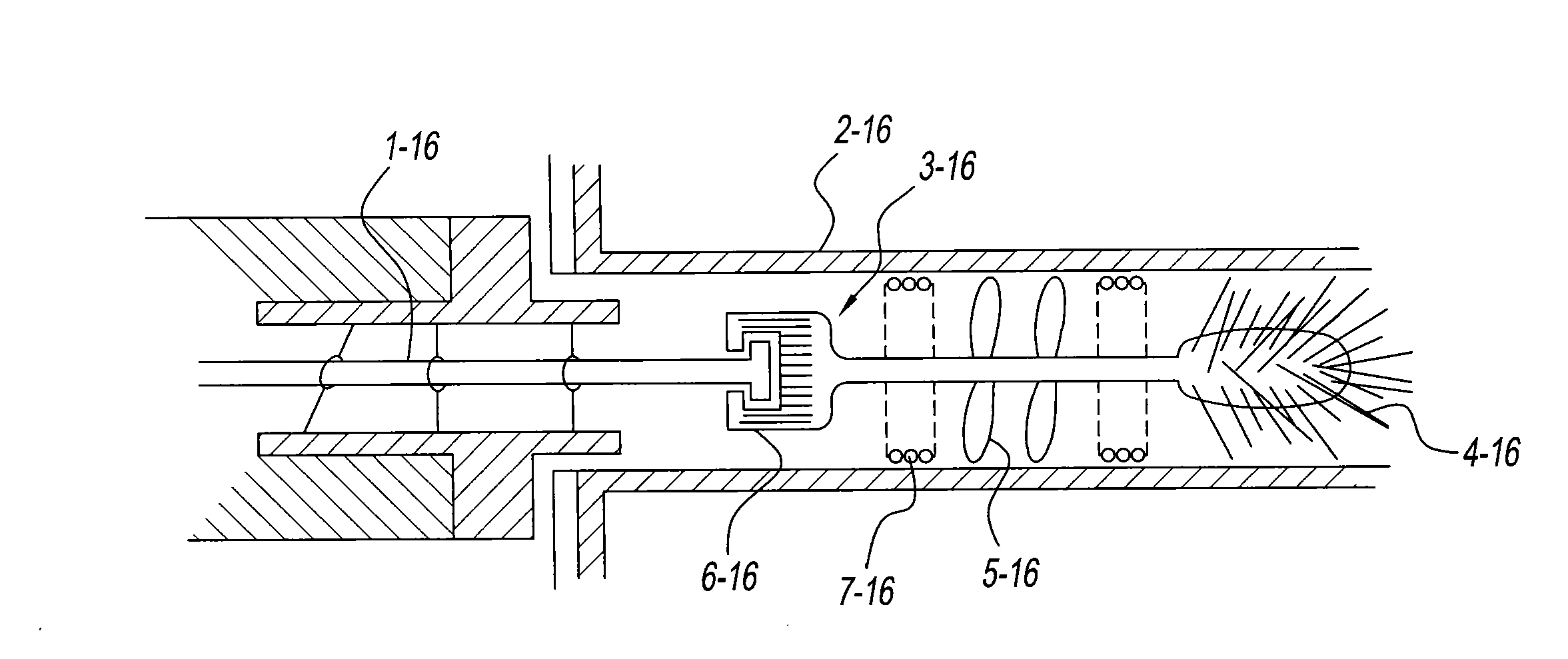
[0052]The present invention relates to a cleaning system used to clean tube and shell heat exchangers. The cleaning system includes multiple mechanical systems. The cleaning system is an online cleaning system and cleans the tubes in the tube and shell heat exchanger while the heat exchanger remains in use. The system also isolates and cleans the tubes one at a time while the other tubes remain online for the heat exchanger to function.

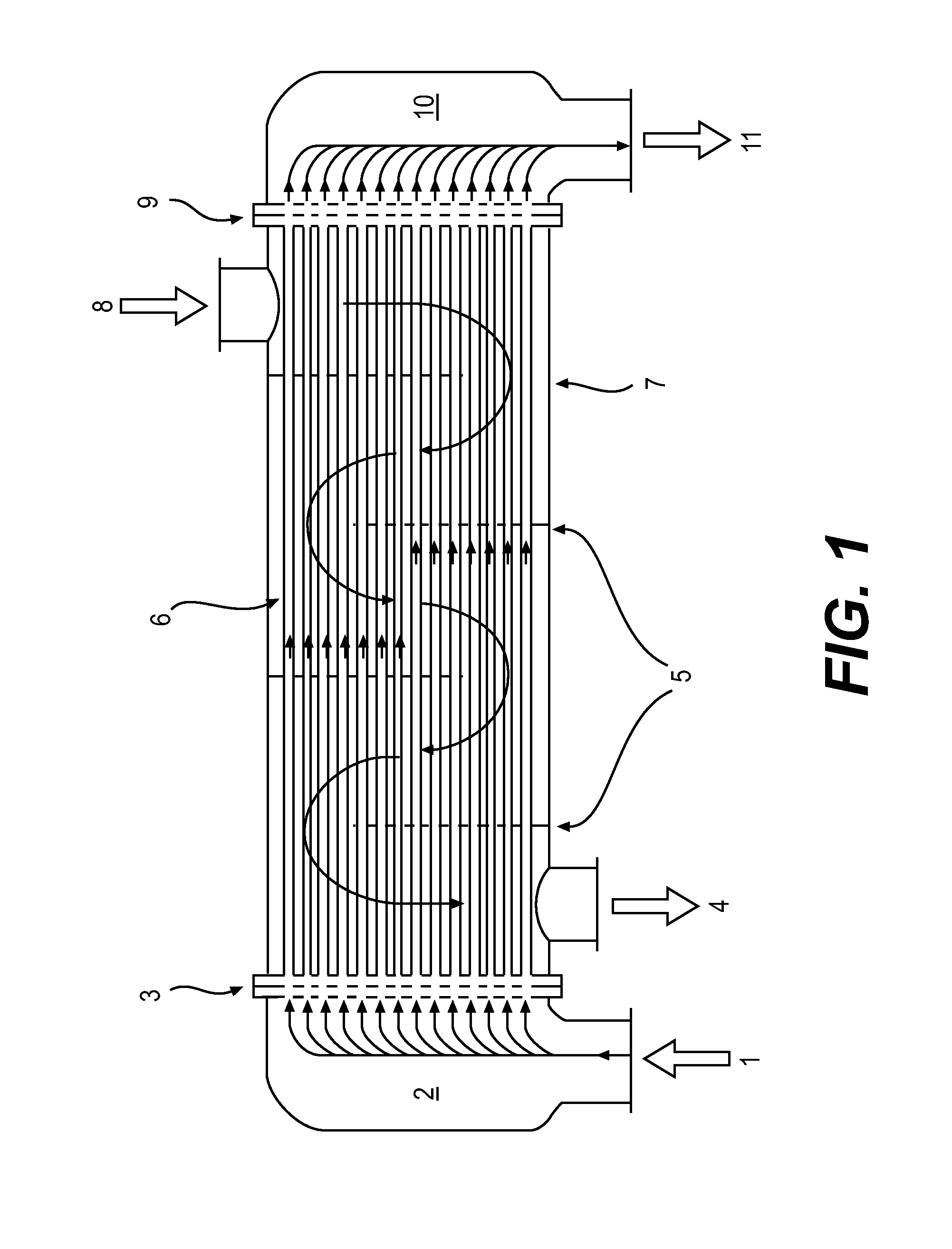
[0053]FIG. 1 illustrates a single-pass tube and shell heat exchanger system. The fluid that flows through the tubes enters through a tube-side 1 into the inlet plenum 2. The fluid then passes through a tube sheet 3 and flows through the straight tube bundles 6. The fluid then passes through a second tube sheet 9 and into the outlet plenum 10 to flow out of the heat exchanger through the passageway 11. The fluid t...


PUM


Abstract

An online cleaning system for tube and shell heat exchangers is presented. The system includes a positioner, a plunger, an umbilical cleaner, and a motor. The cleaning system cleans the tubes while the heat exchanger remains in operation. The cleaning system locates and isolates a single tube via rotating and translating mechanical actions and inserts the umbilical cleaner into the tube, which may clean the tube via rotational movement or via sonication. The cleaning system may further clean the outer surface of the tubes of the heat exchanger.

Description

BACKGROUND OF THE INVENTION[0001]1. Technical Field[0002]The present invention relates to an online cleaning system used to clean a tube and shell heat exchanger including a cleaning system comprising a positioner, a plunger, an umbilical cleaner, and a motor. The cleaning system uses a tube that contains both rotating and translating mechanical actions and cleans while the heat exchanger is in operation.[0003]2. Description of the Related Art[0004]The “background” description provided herein is for the purpose of generally presenting the context of the disclosure. Work of the presently named inventors, to the extent it is described in this background section, as well as aspects of the description which may not otherwise qualify as prior art at the time of filing, are neither expressly or impliedly admitted as prior art against the present invention.[0005]There are several types of heat exchangers used in various industries. A common type is known as a shell and tube type. Modern sh...

Claims


Application Information

Patent Timeline
Patent Type & Authority Applications(United States)
IPC IPC(8): F28G3/04B08B7/02B08B3/14A46B13/02B08B9/053B08B1/04B08B1/00B08B9/057B08B13/00
CPCF28G3/04B08B9/057B08B7/028B08B3/14A46B13/02B08B9/0535B08B1/04B08B1/002B08B13/00
Inventor ALSADAH, JIHAD HASSANMOKHEIMER, ESMAIL M.A.
Owner KING FAHD UNIVERSITY OF PETROLEUM AND MINERALS
Why Eureka
Try Eureka