Image processor

Active Publication Date: 2016-04-28
MEGACHIPS
View PDF6 Cites 11 Cited by
  • Summary
  • Abstract
  • Description
  • Claims
  • Application Information

AI Technical Summary

Benefits of technology

The present disclosure is directed to an image processor that includes an encoder and a decoder. The encoder encodes image data to generate encoded image data, while the decoder decodes the encoded image data. The image processor includes a first memory, an encoding circuit, an error notification receiving circuit, and a first reference image determination circuit. The decoder includes a second memory, a decoding circuit, an error notification sending circuit, and a second reference image determination circuit. The first reference image determination circuit determines to use a local decoded image generated in a vertical synchronization period of two periods before as a reference image, while the second reference image determination circuit determines to use a local decoded image generated in a vertical synchronization period of three periods before as a reference image. The image processor can also include an error notification sending circuit that sends an error notification to the error notification receiving circuit when an error occurs in the decoding circuit. The technical effect of this patent is to improve the accuracy and efficiency of image processing by using reference images generated from nearby vertical synchronization periods.

Problems solved by technology

In such low-delay codecs, when an error occurs in a decoder due to, for example, a communication error, the decoder notifies an encoder of the error.

Method used


Image

  • Image processor
  • Image processor
  • Image processor

Examples


embodiment 1

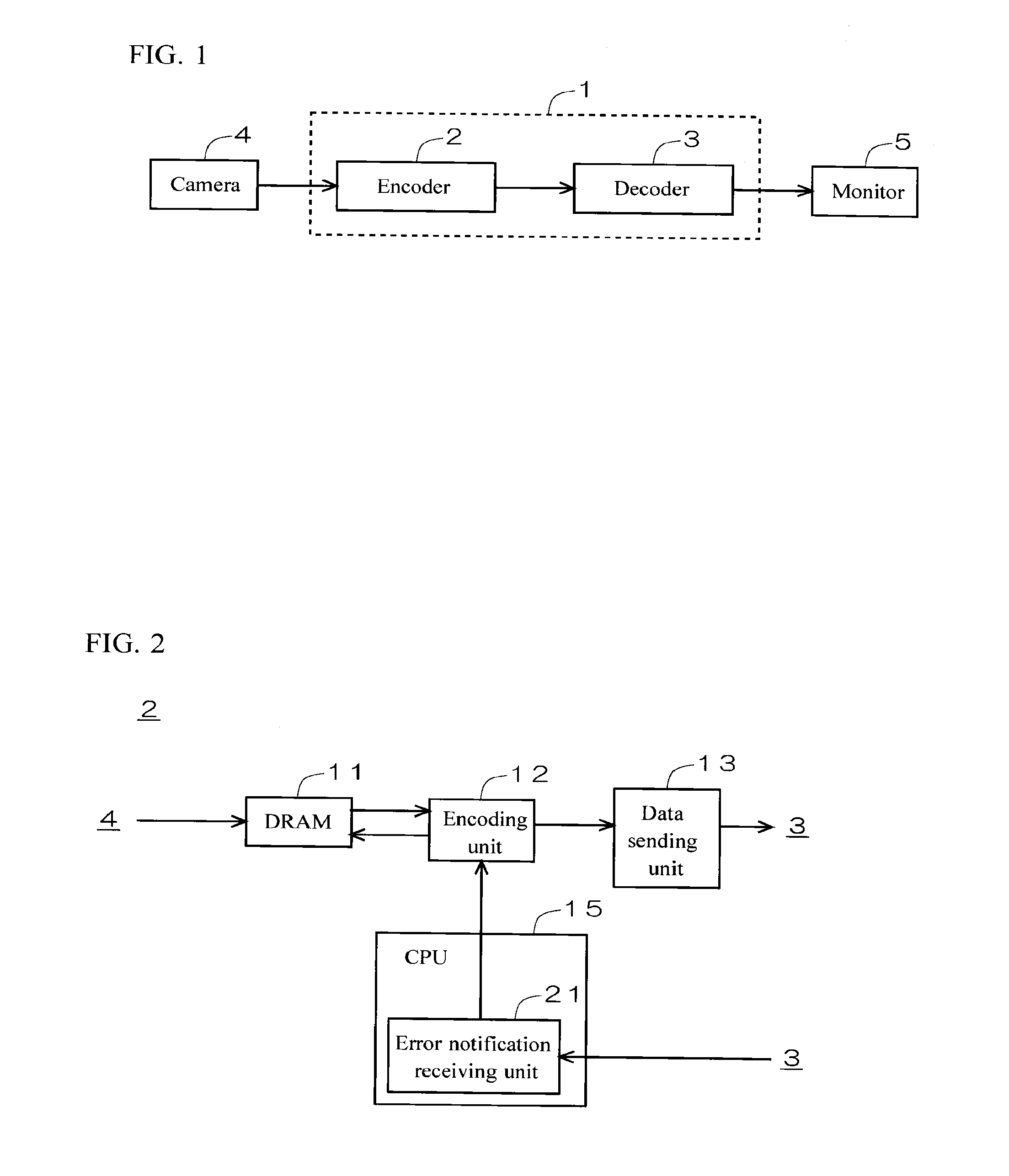
[0055]FIG. 1 is a diagram illustrating a configuration of an image processor 1 according to Embodiment 1 of the present disclosure. As illustrated in FIG. 1, the image processor 1 includes an encoder 2 and a decoder 3. The encoder 2 receives an input of image data of a moving image shot by a camera 4. The encoder 2 encodes the image data input from the camera 4 to generate encoded image data and sends the encoded image data through wired or wireless communication. The decoder 3 decodes the encoded image data received from the encoder 2. The image data decoded by the decoder 3 is input to a monitor 5, and thereby an image is displayed on the monitor 5.

[0056]The image processor 1 is configured as a so-called low-delay codec, in which the encoder 2 in a normal operation generates encoded image data of an intracoded picture (I-picture) for a leading picture input from the camera 4 and encoded image data of predictive-coded pictures (P-picture) for following pictures.

[0057]FIG. 2 is a di...

embodiment 2

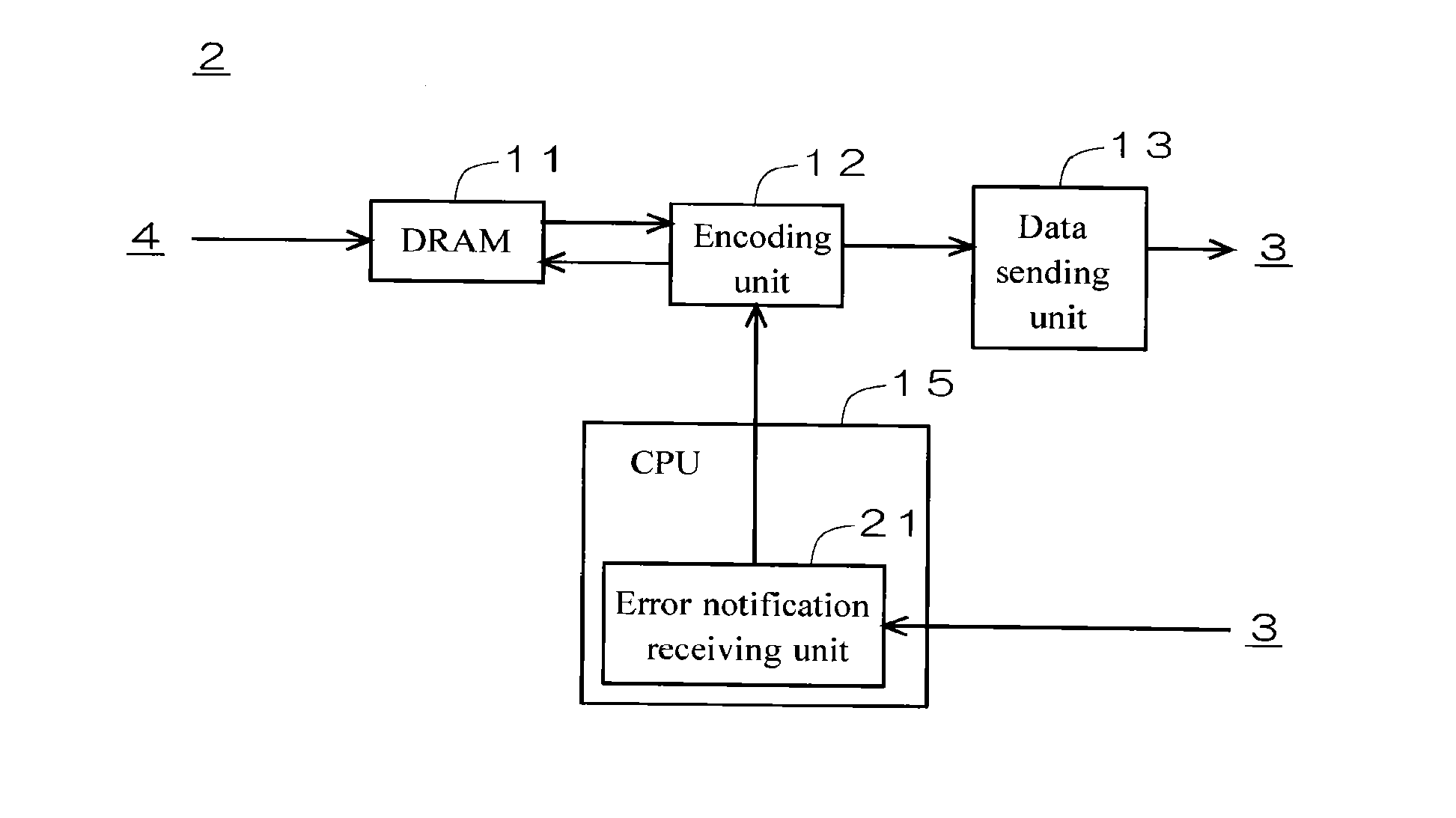
[0070]FIG. 6 is a diagram illustrating a configuration of an encoder 2 according to Embodiment 2 of the present disclosure. As illustrated in FIG. 6, the encoder 2 includes a DRAM 11, an encoding unit 12, a data sending unit 13, a reference image determination unit 14, and a CPU 15. The reference image determination unit 14 may comprise suitable logic, circuitry, interfaces, and / or code. The CPU 15 runs a predetermined program to function as an error notification receiving unit 21. The DRAM 11 stores multiple local decoded images generated by the encoding unit 12 in a predetermined number of (at least three) nearest neighboring vertical synchronization periods.

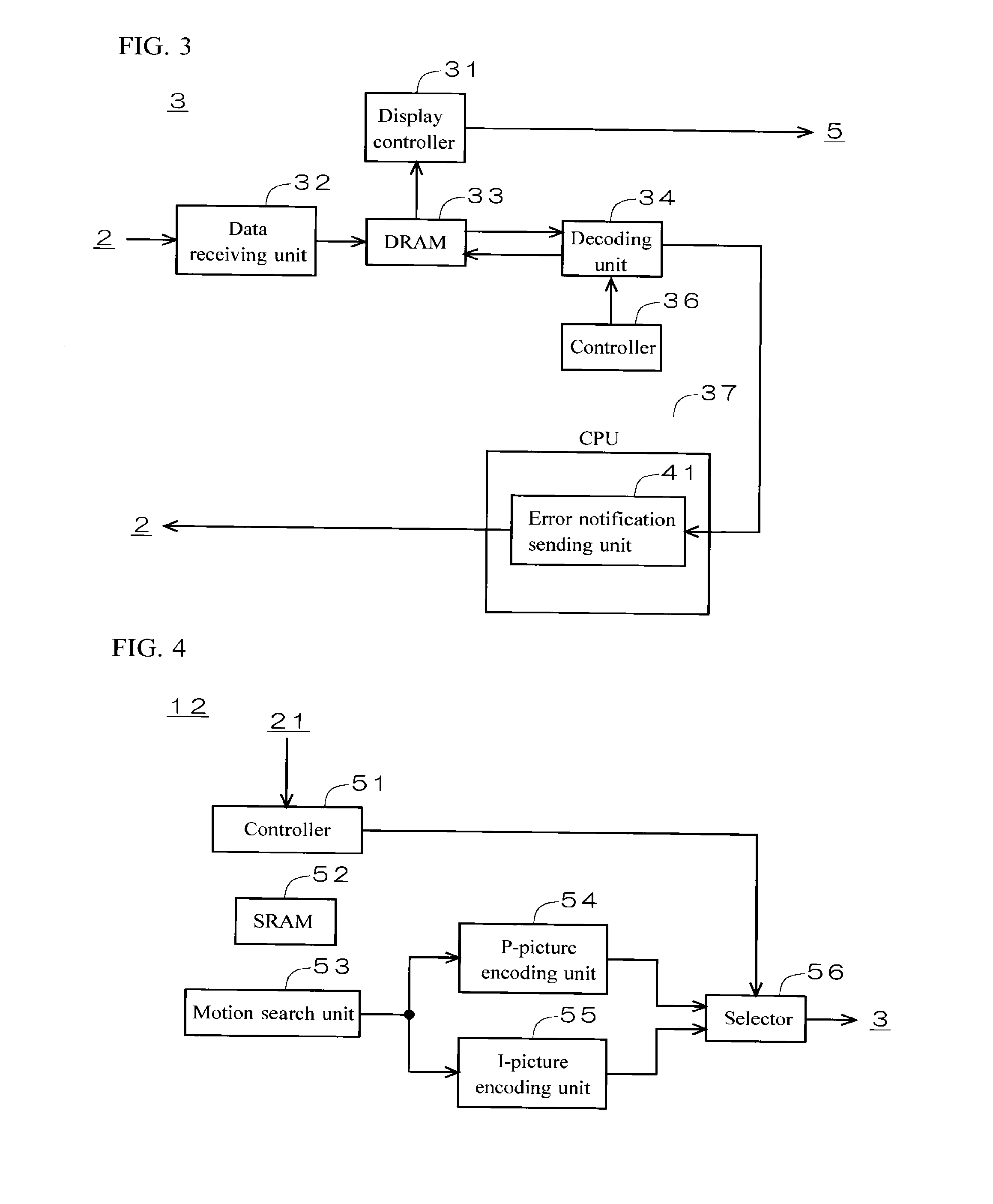
[0071]FIG. 7 is a diagram illustrating a configuration of a decoder 3 according to Embodiment 2. As illustrated in FIG. 7, the decoder 3 includes a display controller 31, a data receiving unit 32, a DRAM 33, a decoding unit 34, a reference image determination unit 35, a controller 36, and a CPU 37. The reference image determin...

embodiment 3

[0089]The configuration of the encoder 2 and the decoder 3 according to Embodiment 3 of the present disclosure is the same as that illustrated in FIGS. 6 and 7.

[0090]FIG. 9 is a diagram for illustrating processing in occurrence of an error in the decoding unit 34. (A) represents image data to be encoded by the encoding unit 12, (B) represents image data to be sent from the data sending unit 13 to the data receiving unit 32, (C) represents image data to be decoded by the decoding unit 34, and (D) represents image data to be displayed on the monitor 5 by the display controller 31. FIG. 9 exemplifies a case where an error occurs while the decoding unit 34 is decoding image data D12 in the vertical synchronization period T12.

[0091]In normal processing in an absence of an error in the decoding unit 34, in the encoder 2, the reference image determination unit 14 determines to employ a local decoded image generated in a vertical synchronization period of two periods before as a reference i...


PUM


Abstract

In an earliest vertical synchronization period after sending an encoded image data is restarted, a first reference image determination circuit determines to employ a local decoded image generated in a vertical synchronization period immediately preceding a vertical synchronization period in which an error occurs among multiple local decoded images stored in a first DRAM as a reference image. In an earliest vertical synchronization period after a decoding circuit is reset, a second reference image determination circuit determines to employ a decoded image generated in the vertical synchronization period immediately preceding the vertical synchronization period in which the error occurs among multiple decoded images stored in a second DRAM as a reference image.

Description

CROSS REFERENCE TO RELATED APPLICATIONS[0001]The present application is based on, and claims priority from Japanese Patent Application Serial Numbers 2014-217812 and 2014-217813, the disclosure of which is hereby incorporated by reference herein in its entirety.BACKGROUND[0002]1. Technical Field[0003]The present disclosure relates to an image processor and more particularly, to a low-delay codec.[0004]2. Related Art[0005]Low-delay codecs which keep a constant communication rate by employing an intracoded picture (I-picture) only for the leading picture and predictive-coded pictures (P-picture) for all following pictures are in actual use.[0006]In such low-delay codecs, when an error occurs in a decoder due to, for example, a communication error, the decoder notifies an encoder of the error. The encoder that is notified of the error generates coded data of an I-picture as a leading picture after error notification and coded data of P-pictures as following pictures. Then the coded dat...

Claims


Application Information

Patent Timeline
IPC IPC(8): H04N19/65H04N19/423H04N19/44
CPCH04N19/65H04N19/423H04N19/44H04N19/105H04N19/164H04N19/172
Inventor YAMAMURA, NAOTSUGUOKAMOTO, AKIRATAKASU, NOBUYUKI
Owner MEGACHIPS
Why Eureka
Try Eureka