Bifurcation honeycomb sandwich structure with optimized doubler

a honeycomb ribbon and sandwich structure technology, applied in the direction of manufacturing tools, transportation and packaging, aircraft power plant components, etc., can solve the problems of honeycomb ribbon structure buckles, deformations to an unacceptable level, and halt the forming process

Active Publication Date: 2016-05-05
SPIRIT AEROSYSTEMS
View PDF3 Cites 3 Cited by
  • Summary
  • Abstract
  • Description
  • Claims
  • Application Information

AI Technical Summary

Benefits of technology

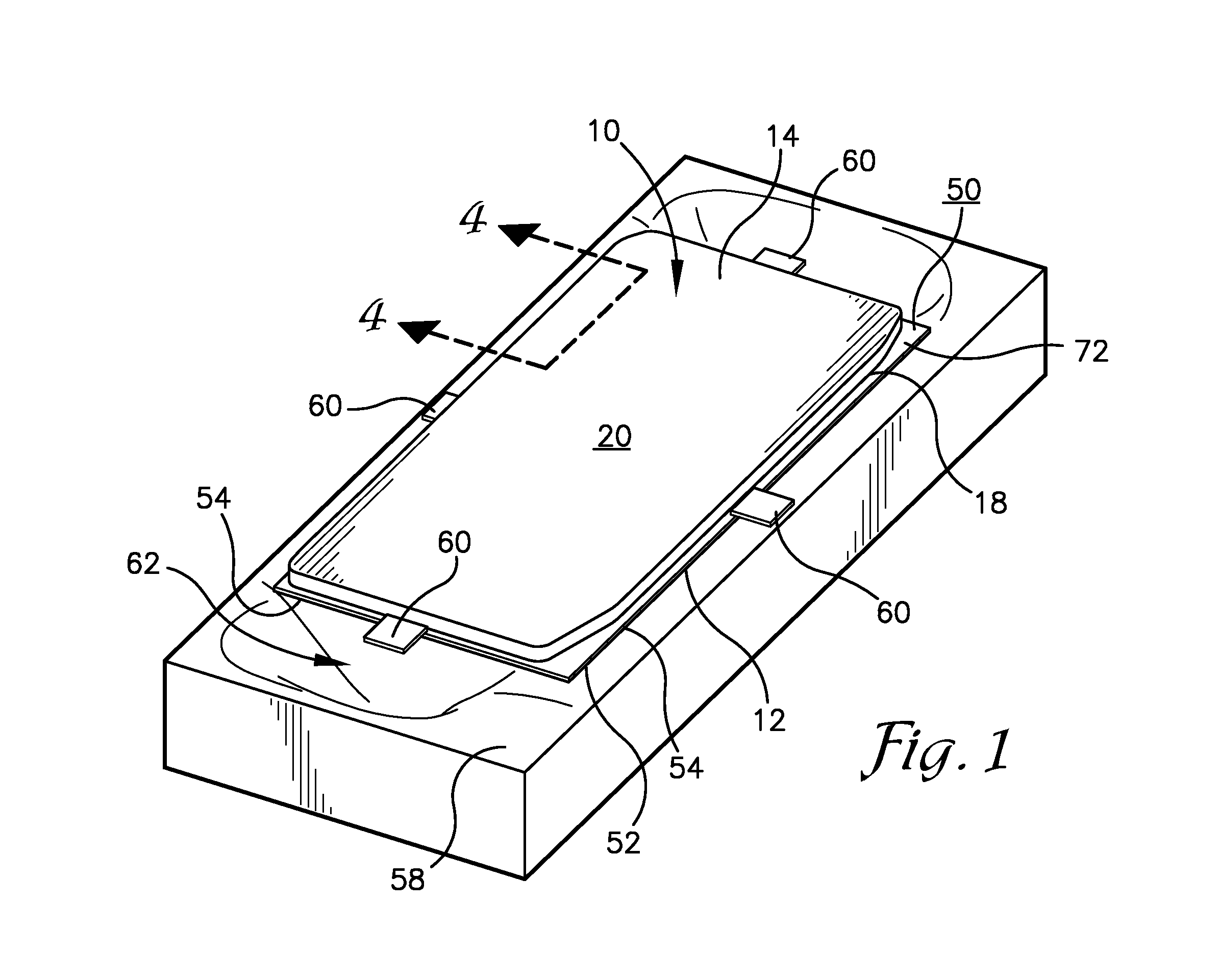
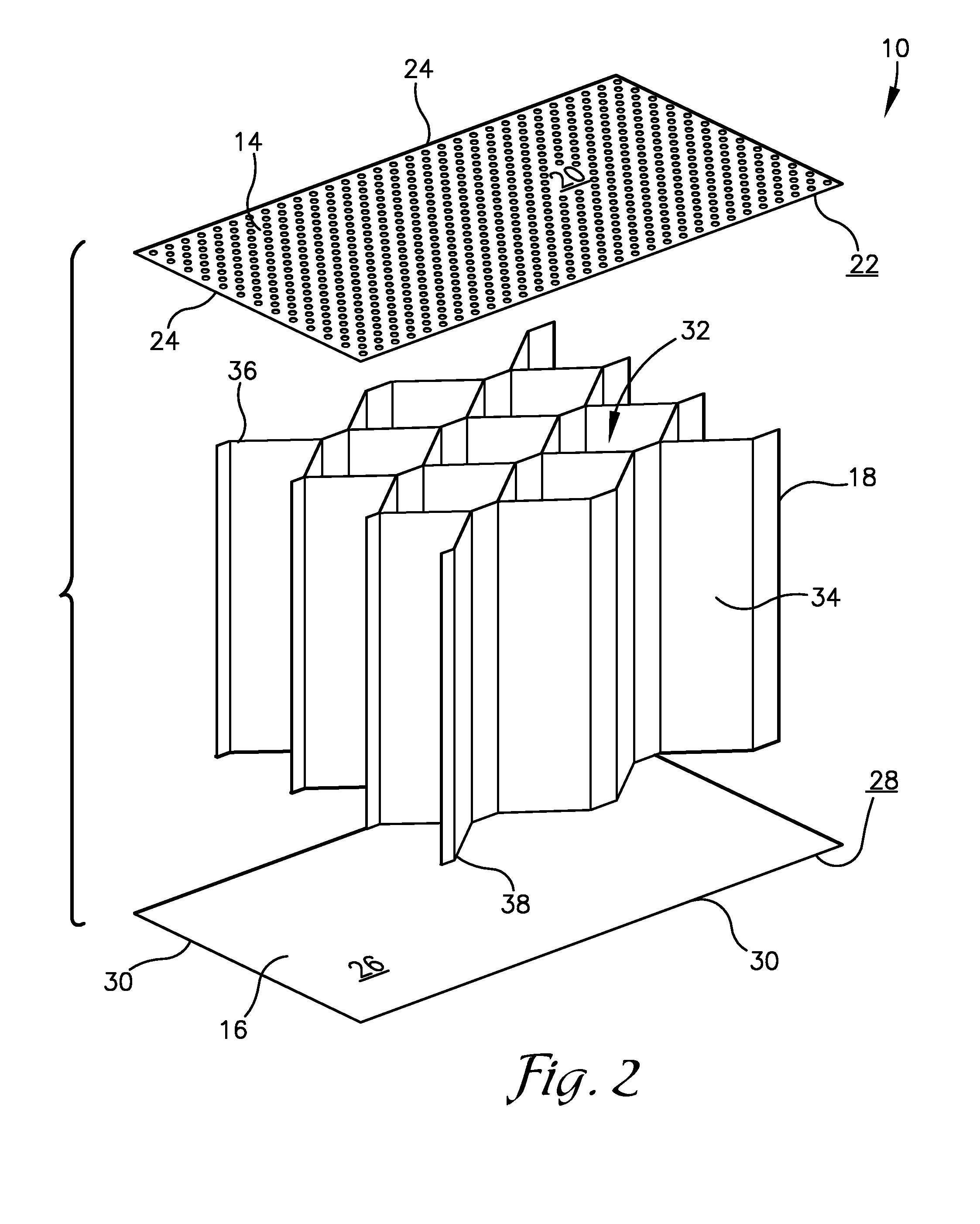
The present invention provides a method of shaping metallic honeycomb panels using a continuous sacrificial drive sheet. This method can be used to create metallic honeycomb panels with complex shapes, such as bifurcation panels for aircraft nacelles. The method involves welding the drive sheet to the lower sheet of the panel, heating the panel and drive sheet to a forming temperature, and using a male or female die mold to shape the panel. The drive sheet is designed to cover all of the lower sheet and has varying thicknesses based on the criteria and finite element analysis. The cooling and cutting steps are also provided. The technical effects of this invention include the ability to create complex honeycomb panels with accurate shapes using a continuous drive sheet and the use of heating and shaping techniques to achieve high-quality results.

Problems solved by technology

Unfortunately, the welds between the doubler and the solid lower sheet of the bifurcation panel often leak, which may halt the forming process due to the release of forming pressure.
In addition, uneven application of forming force at discrete locations on the doubler or pull tabs may result in stresses which cause the honeycomb ribbon structure to buckle and deform to an unacceptable level.

Method used


Image

  • Bifurcation honeycomb sandwich structure with optimized doubler
  • Bifurcation honeycomb sandwich structure with optimized doubler
  • Bifurcation honeycomb sandwich structure with optimized doubler

Examples


Embodiment Construction

[0015]The following detailed description of the invention references the accompanying drawings that illustrate specific embodiments in which the invention can be practiced. The embodiments are intended to describe aspects of the invention in sufficient detail to enable those skilled in the art to practice the invention. Other embodiments can be utilized and changes can be made without departing from the scope of the current invention. The following detailed description is, therefore, not to be taken in a limiting sense. The scope of the current invention is defined only by the appended claims, along with the full scope of equivalents to which such claims are entitled.

[0016]In this description, references to “one embodiment”, “an embodiment”, or “embodiments” mean that the feature or features being referred to are included in at least one embodiment of the technology. Separate references to “one embodiment”, “an embodiment”, or “embodiments” in this description do not necessarily ref...


PUM

PropertyMeasurementUnit
Thicknessaaaaaaaaaa
Shapeaaaaaaaaaa
Dimensionaaaaaaaaaa

Abstract

A method of shaping a metallic honeycomb panel using a continuous drive sheet. The metallic honeycomb panel may have a perforated upper sheet, a non-perforated lower sheet, and a metal honeycomb core fixed between the upper and lower sheets. The method may include the steps of designing and manufacturing the drive sheet using finite element analysis (FEA) and criteria regarding shaping of the metallic honeycomb panel, then welding the drive sheet to the lower face of the lower sheet. The drive sheet may cover all of the lower face of the lower sheet and may have varying thicknesses determined based on the criteria and the FEA. The method may also include the steps of heating the drive sheet and metallic honeycomb panel to a creep forming or hot-stretch forming temperature and urging the metallic honeycomb panel and drive sheet into a male or female die mold to be shaped.

Description

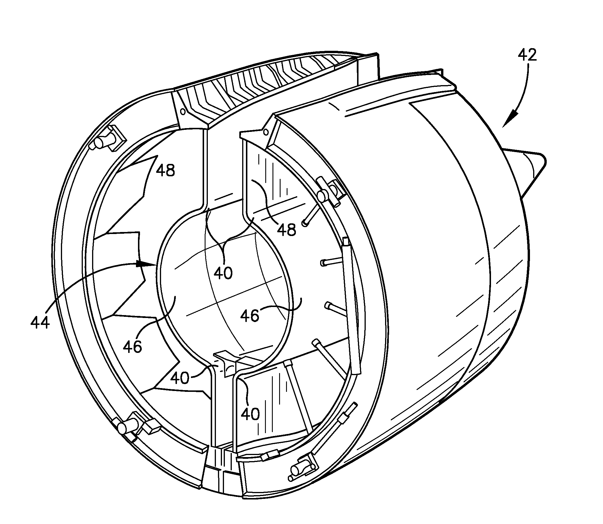
BACKGROUND[0001]Many aircrafts have engines supported by struts protruding from each wing. The engines are each surrounded by various structural and control components, such as a fan duct and / or a thrust reverser. To provide access to the engine for maintenance or repair, the fan duct and thrust reverser are constructed in two halves which can pivot upward about large hinge pins at the strut. Specifically, an inner acoustic wall of the fan duct may include two clam-shell portions cooperatively forming the fan duct. At facing edges of the clam-shell portions, where the two halves attach to each other and / or to the aircraft, flanges extend radially outward therefrom for attachment to the strut. A curved portion of the fan duct's inner acoustic wall, where the flanges meet with the clam-shell portions, may be referred to herein as a bifurcation panel. Each of the bifurcation panels may be welded, mechanically fastened, or otherwise fixed between the flanges and the clam-shell portions....

Claims


Application Information

Patent Timeline
IPC IPC(8): B64D29/02B23K31/02
CPCB23K31/02B64D29/02B21D47/04
Inventor NASSERRAFI, RAHBARWADE, DARRELL A.LE, THANH A.
Owner SPIRIT AEROSYSTEMS
Why Eureka
Try Eureka