Ultrasonic measurement apparatus, ultrasonic diagnostic apparatus, and ultrasonic measurement method

a technology of ultrasonic diagnostic apparatus and measurement apparatus, applied in the direction of measuring devices, using reradiation, instruments, etc., can solve the problems of degrading the resolution of the obtained image, not being able to capture a signal other than the plane wave, etc., and achieve the effect of improving the resolution of the obtained signal (image)

Active Publication Date: 2016-05-05
SEIKO EPSON CORP
View PDF0 Cites 5 Cited by
  • Summary
  • Abstract
  • Description
  • Claims
  • Application Information

AI Technical Summary

Benefits of technology

[0008]An advantage of some aspects of the invention is to provide an ultrasonic measurement apparatus, an ultrasonic diagnostic apparatus, and an ultrasonic measurement method in which resolution of an obtained signal (image) can be improved by performing phasing processing which varies in accordance with whether a signal processing target point exists in a plane wave propagation region or a spherical wave propagation region.
[0010]According to the aspect of the invention, the phasing processing is changed in accordance with whether the signal processing target point exists in the plane wave propagation region or exists in the spherical wave propagation region. Even when the plane wave is transmitted, a region having the spherical wave propagated is generated. However, since information corresponding to the spherical wave propagation region can also be suitably utilized in generation processing of an output signal, it is possible to improve resolution of a signal (an image).
[0026]With this configuration, it is possible to perform processing for obtaining a synthetic signal by synthesizing a reception signal which is acquired from each element among a plurality of elements.

Problems solved by technology

According to the technique disclosed in Non Patent Literature 1, it is not possible to capture a signal of a wave other than the plane wave.
Therefore, an aperture width effective for transmission becomes small in the technique, thereby leading to a disadvantage in that resolution of an obtained image is degraded as a result thereof.

Method used


Image

  • Ultrasonic measurement apparatus, ultrasonic diagnostic apparatus, and ultrasonic measurement method
  • Ultrasonic measurement apparatus, ultrasonic diagnostic apparatus, and ultrasonic measurement method
  • Ultrasonic measurement apparatus, ultrasonic diagnostic apparatus, and ultrasonic measurement method

Examples


Embodiment Construction

[0051]Hereinafter, an embodiment will be described. The below-described embodiment does not unjustly limit the contents of the invention disclosed in aspects of the invention. All the configurations described in the embodiment are not necessarily the essential configuration element of the invention.

1. Technique of Embodiment

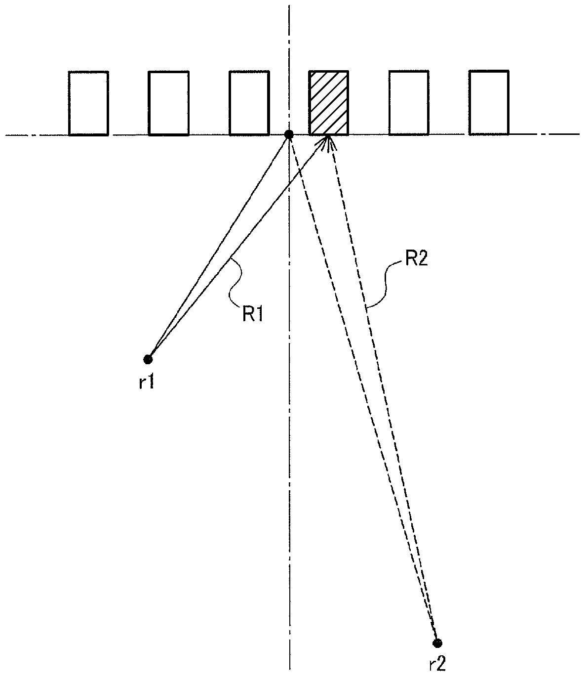
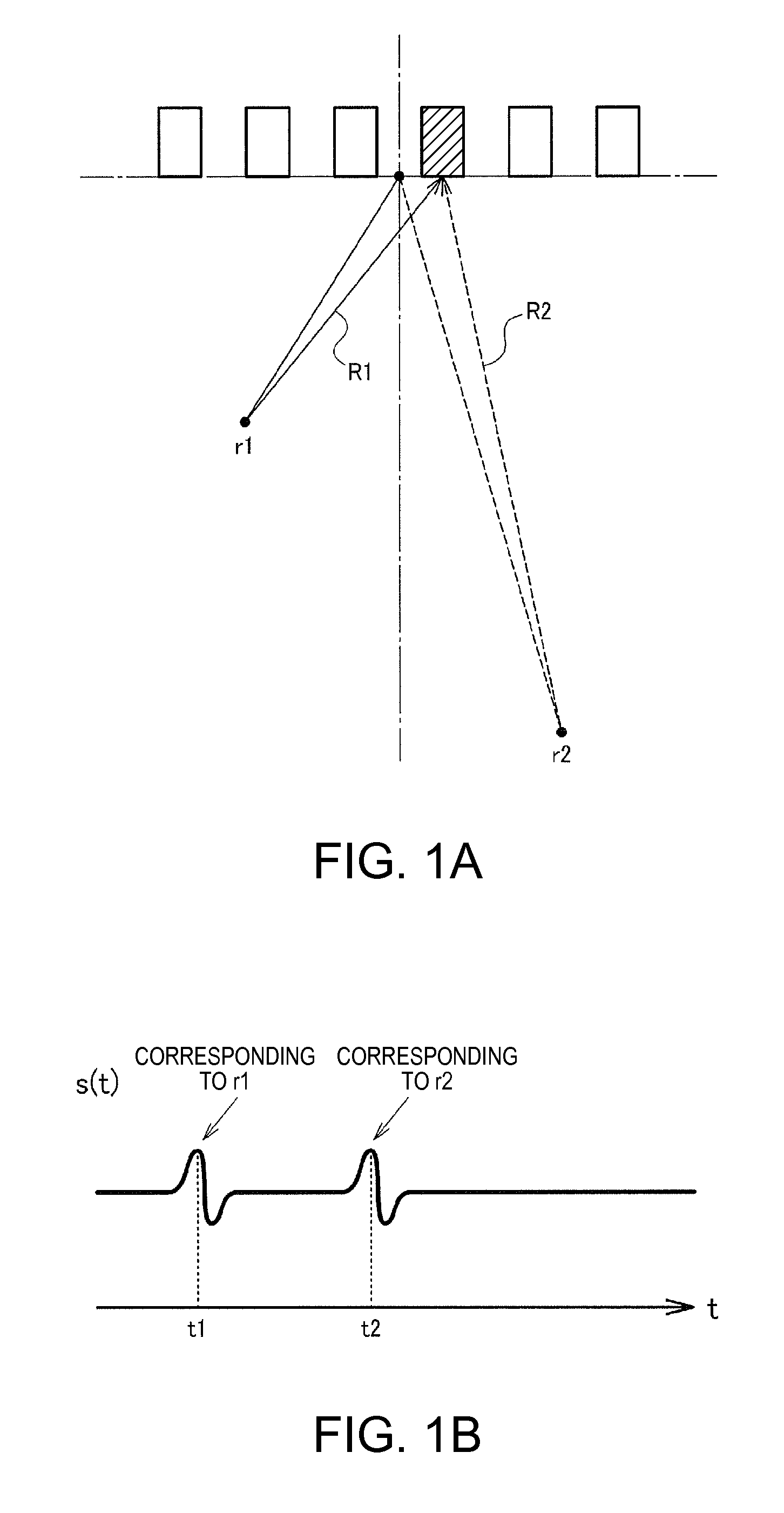
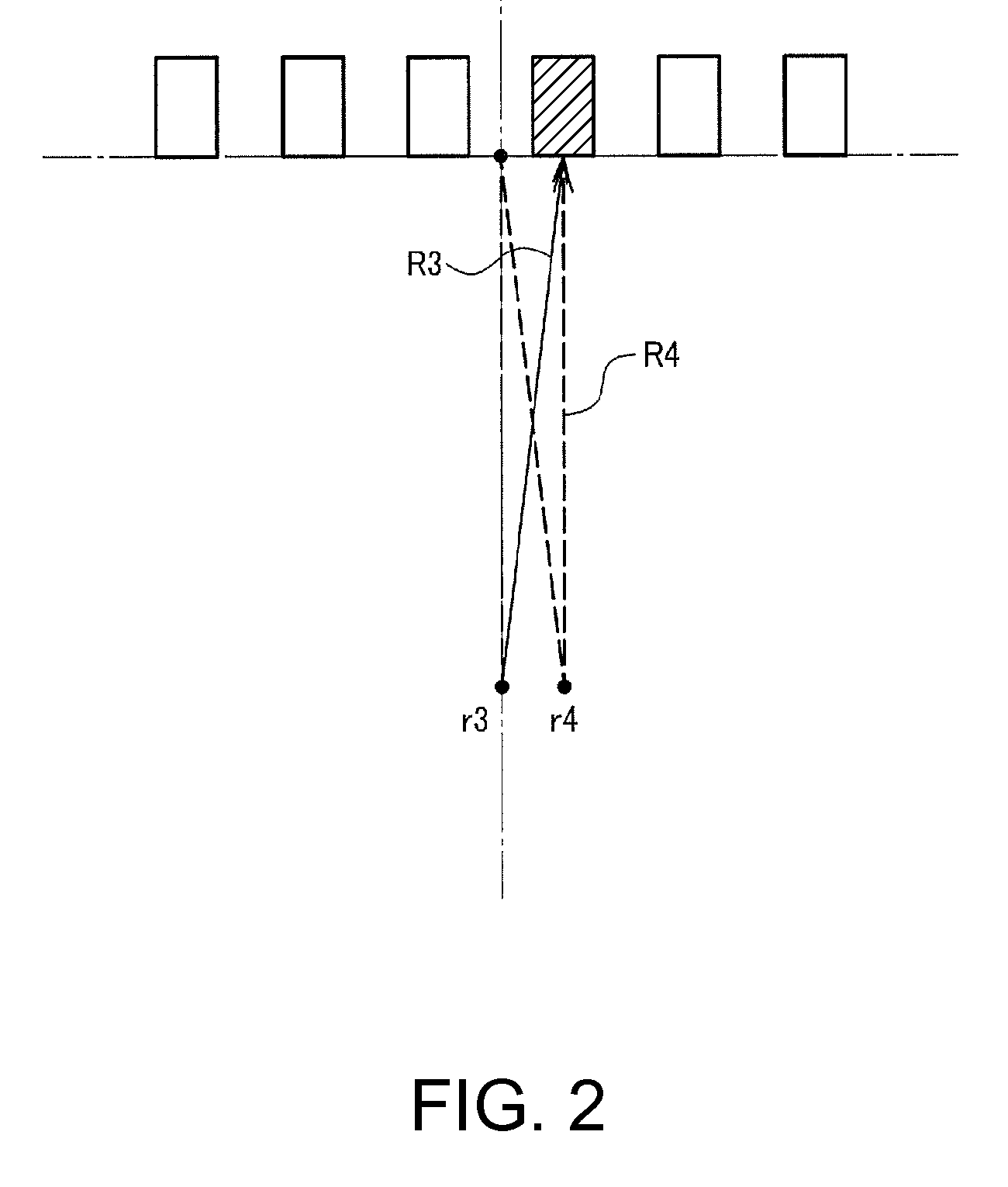
[0052]Firstly, technique of the embodiment will be described. Regarding technique of performing transmission and reception of a signal in an ultrasonic measurement apparatus, there is known technique of focusing on a given measurement point at the time of transmitting an ultrasonic wave signal. For example, with respect to each of the elements in an element array (for example, corresponding to an ultrasonic transducer device described below in FIGS. 13 to 14B) including a plurality of ultrasonic transducer elements 10, a corresponding delay is applied to each of the elements at the time of driving. Since an ultrasonic wave transmitted by such technique focuses on...


PUM


Abstract

An ultrasonic measurement apparatus includes a transmission processing unit that performs processing for transmitting an ultrasonic wave at a given transmission angle, a reception processing unit that performs reception processing of an ultrasonic echo with respect to the transmitted ultrasonic wave in first to Nth (N is an integer equal to or greater than 2) ultrasonic transducers; and a processing unit that performs processing with respect to first to Nth reception signals corresponding to the first to Nth ultrasonic transducers. The processing unit performs first phasing processing when a signal processing target point exists in a plane wave propagation region, and performs second phasing processing when the signal processing target point exists in a spherical wave propagation region, as phasing processing with respect to each of the reception signals of the first to Nth reception signals.

Description

BACKGROUND[0001]1. Technical Field[0002]The present invention relates to an ultrasonic measurement apparatus, an ultrasonic diagnostic apparatus, an ultrasonic measurement method, and the like.[0003]2. Related Art[0004]In ultrasonic measurement apparatuses (ultrasonic diagnostic apparatuses), synthetic aperture processing in which focusing can be formed in overall region of an observation region is adopted thereto in order to obtain favorable resolution throughout a wide region in an ultrasonic image. According to the aforementioned technique, focusing can be formed with the fewer number of times of transmissions and receptions, and processing is performed so as to be able to attain a high frame rate and high resolution.[0005]Among methods of the synthetic aperture processing, there is known technique in which plane waves are used as transmission waves. For example, JP-A-2003-220059 discloses technique of performing the synthetic aperture processing in consideration of diffraction c...

Claims


Application Information

Patent Timeline
Patent Type & Authority Applications(United States)
IPC IPC(8): G01S15/89
CPCG01S15/89G01S15/8915G01S7/52046G01S15/8913
Inventor MASUDA, HIROYUKI
Owner SEIKO EPSON CORP
Why Eureka
Try Eureka