
Three-dimensional display system

Active Publication Date: 2016-05-05
BOE TECH GRP CO LTD
View PDF6 Cites 8 Cited by
  • Summary
  • Abstract
  • Description
  • Claims
  • Application Information

AI Technical Summary

Benefits of technology

The three-dimensional display system described in this patent allows for adjustable viewing distance by using a refractive index adjusting device between the display device and the three-dimensional grating. This results in a more adaptable and versatile display system that can be used in a wider range of applications.

Problems solved by technology

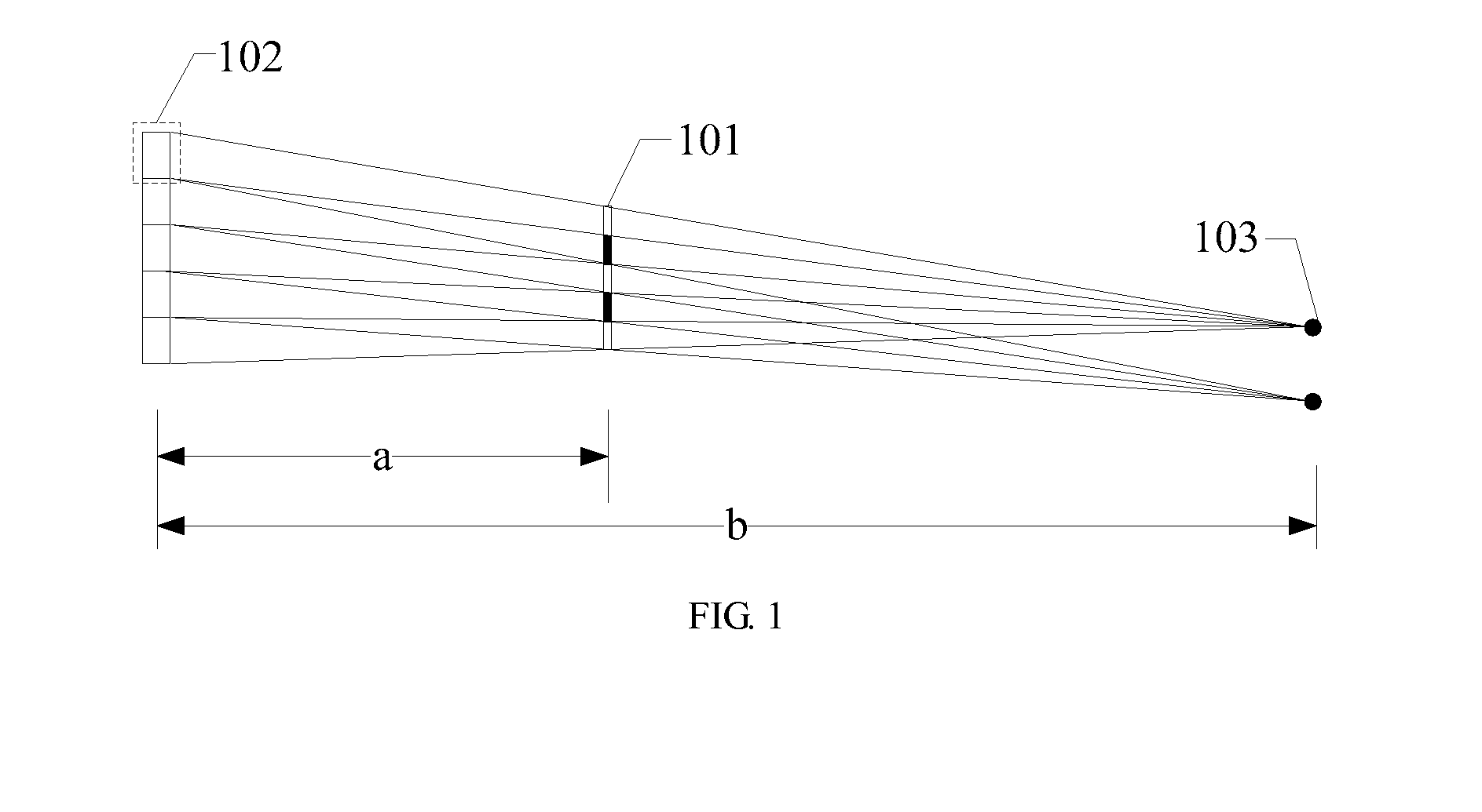
When the viewer views the display panel at a distance other than the viewing range b, a problem of crosstalk may occur, affecting a 3D display effect.

Method used


Image

  • Three-dimensional display system
  • Three-dimensional display system
  • Three-dimensional display system

Examples


Embodiment Construction

[0011]In order to make objects, technical details and advantages of the embodiments of the invention apparent, the technical solutions of the embodiment will be described in a clearly and fully understandable way in connection with the drawings related to the embodiments of the invention. It is obvious that the described embodiments are just a part but not all of the embodiments of the invention. Based on the described embodiments herein, those skilled in the art can obtain other embodiment(s), without any inventive work, which should be within the scope of the invention.

[0012]Hereinafter, a three-dimensional display system provided by an embodiment of the present invention will be described in detail in conjunction with accompanying drawings.

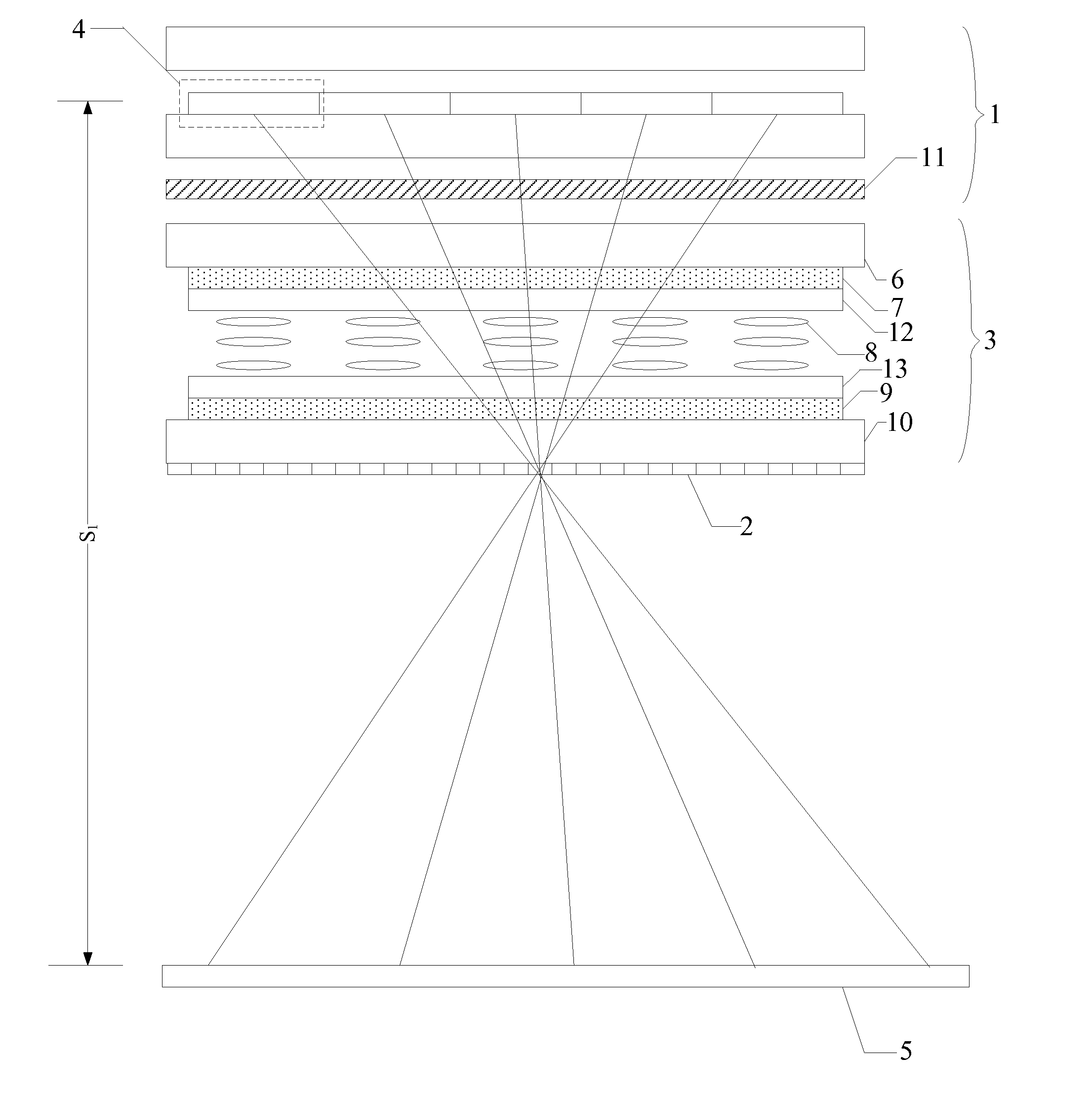
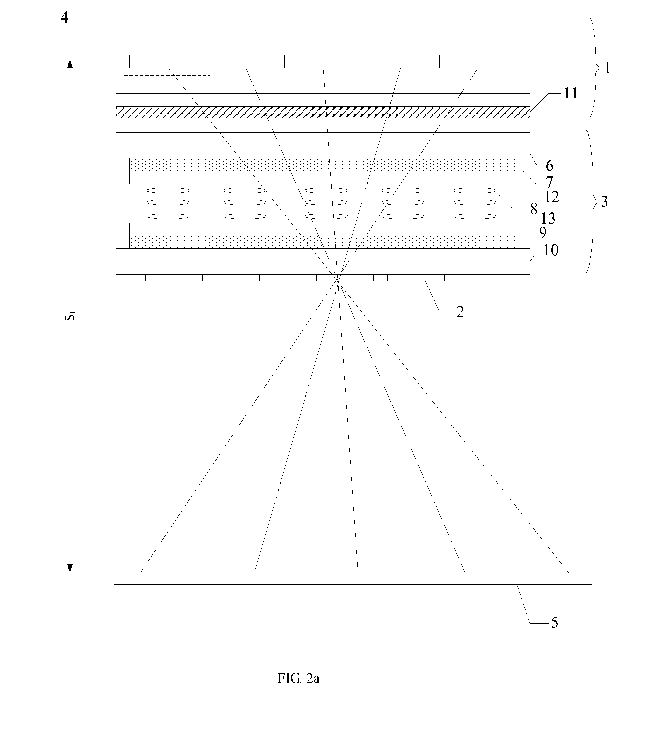
[0013]The three-dimensional display system provided by the embodiment of the present invention, as shown in FIG. 2a and FIG. 2b, comprises: a display device 1; a three-dimensional grating 2 located on a light emitting side of the display device...


PUM


Abstract

A three-dimensional display system is provided, comprising: a display device; a three-dimensional grating, located on a light emitting side of the display device; and a refractive index adjusting device, disposed between the display device and the three-dimensional grating, wherein the refractive index adjusting device adjusts a viewing distance of the three-dimensional display system by changing a refractive index of outgoing light emitted from the display device to the three-dimensional grating. The viewing distance of the three-dimensional display system is changeable, so that the three-dimensional display system has enhanced space adaptability and a wider application range.

Description

TECHNICAL FIELD[0001]Embodiments of the present invention relate to a three-dimensional display system.BACKGROUND[0002]Currently, a three-dimensional (3D) display technology has been a matter of great concern. In order to implement 3D display, a frequently-used 3D technology is to dispose a three-dimensional grating on a light emitting side of a display panel. The three-dimensional grating may be divided into an active grating and a passive grating, wherein, the active grating includes a liquid crystal slit grating, a liquid crystal lens grating and the like, and the passive grating includes a cylindrical lens grating and a slit grating, etc.[0003]As shown in FIG. 1, it is illustrated with a case where a slit grating 101 is disposed on the light emitting side of the display panel as an example, light emitted from different sub-pixel units 102 (FIG. 1 is illustrated by taking 5 sub-pixel units as an example) in the display panel are projected into different viewing fields, and two ey...

Claims


Application Information

Patent Timeline
IPC IPC(8): G02B27/22G02F1/1337G02B27/42G02B30/25G02B30/28
CPCG02B27/22G02B27/4205G02F2001/133757G02F1/133753G02F1/133784G02F2201/30H04N13/315H04N13/373G02B30/25G02B30/28G02B30/27G02F1/133757
Inventor WEI, WEI
Owner BOE TECH GRP CO LTD
Learn More