Image forming apparatus, image forming system and concentration unevenness detecting method

an image forming system and detecting method technology, applied in the field of electrographic image forming apparatus, image forming system, concentration unevenness detection method, can solve the problems of concentration unevenness, concentration unevenness, deterioration of image quality of output image (image formed on paper sheet)

Active Publication Date: 2016-05-05
KONICA MINOLTA INC
View PDF0 Cites 15 Cited by
  • Summary
  • Abstract
  • Description
  • Claims
  • Application Information

AI Technical Summary

Benefits of technology

[0013]An object of the present invention is to provide an image forming apparatus, an image forming system, and a concentration unevenness detecting method which can surely detect concentration unevenness in the vertical scanning direction.

Problems solved by technology

There is a problem in that, in this image forming apparatus, the image quality of the output image (image formed on the paper sheet) is deteriorated by deterioration of the photoreceptor drum, developer, and the like with time, the ambient environment of the device (change of temperature and humidity), and the like.
Further, in the image forming apparatus, there is a case where concentration unevenness in the circumferential direction (vertical scanning direction) is generated in the toner image formed on the photoreceptor drum.
The concentration unevenness is caused by change of the distance between the photoreceptor drum and a developing roller due to rotational deflection of the developing roller and humidity unevenness in the rotary axis direction of the photoreceptor drum.
Accordingly, the charge cannot be normally performed, and the humidity unevenness is generated.
However, regarding the technique disclosed in JP 2014-116711 A, it is necessary to separately print a test chart during normal image forming processing, and accordingly, the decrease of productivity has been a problem.
However, since the concentration unevenness is generated at various cycles such as a cycle of the developing roller and a cycle of the photoreceptor drum, it is necessary to use a paper gap having a certain size (a region between an image forming region where the toner image to be transferred to a single paper sheet is formed and another image forming region, and a region where the concentration change detecting pattern is formed) to detect the concentration unevenness.
The concentration unevenness cannot be sufficiently detected according to the size of the paper gap.
There are many cases where the size of the concentration change detecting pattern which can be formed in the margin is not large enough to detect the concentration unevenness at one time.

Method used


Image

  • Image forming apparatus, image forming system and concentration unevenness detecting method
  • Image forming apparatus, image forming system and concentration unevenness detecting method
  • Image forming apparatus, image forming system and concentration unevenness detecting method

Examples


Embodiment Construction

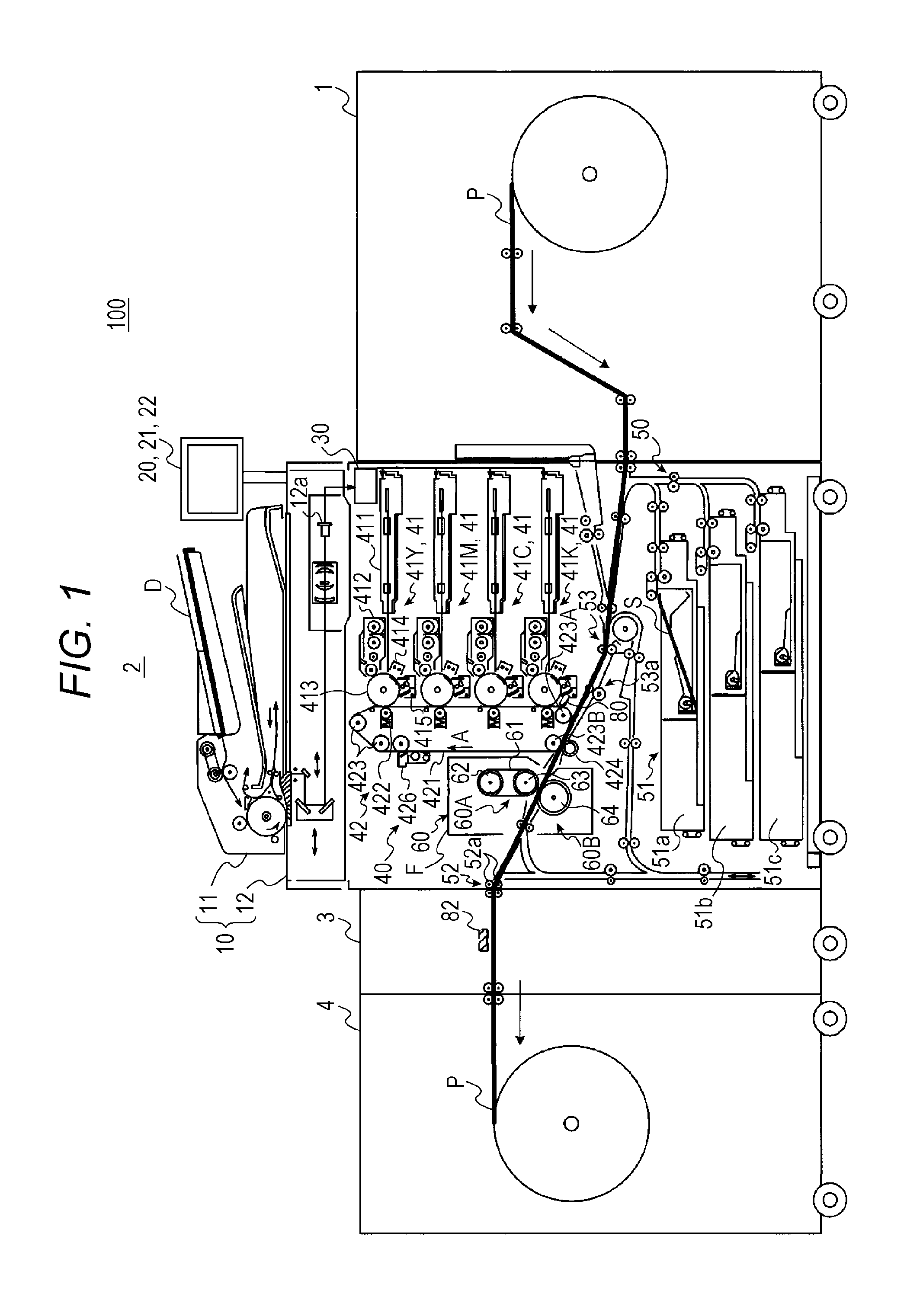
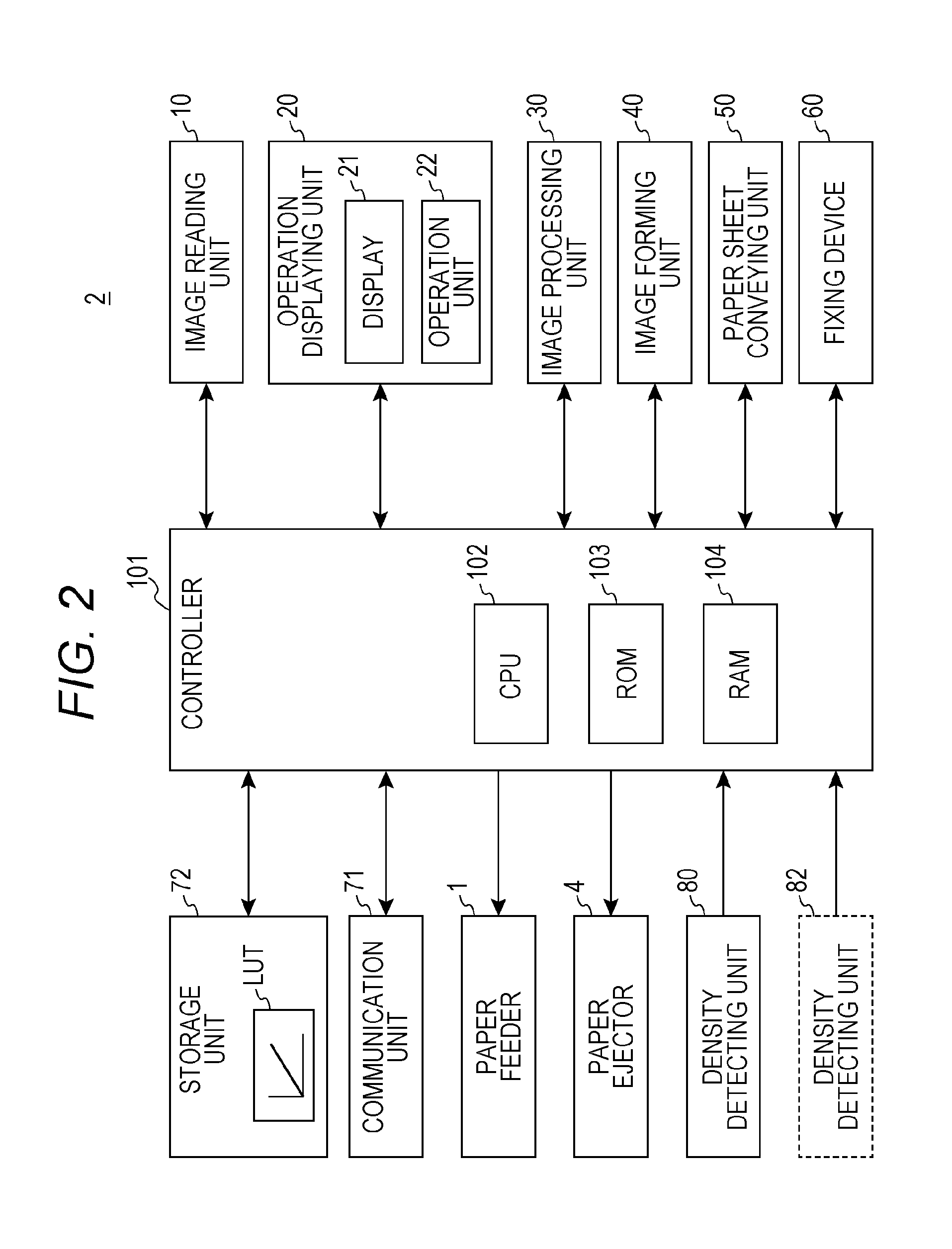
[0024]Hereinafter, an embodiment of the present invention will be described in detail with reference to the drawings. However, the scope of the invention is not limited to the illustrated examples. FIG. 1 is a schematic diagram of a whole structure of an image forming system 100 according to the present embodiment. FIG. 2 is a diagram of a main part of a control system of an image forming apparatus 2 included in the image forming system 100 according to the present embodiment. The image forming system 100 uses a long paper sheet P indicated by a heavy line in FIG. 1 or a paper sheet (also, referred to as “cut sheet”) S which is cut into a predetermined paper size as recording media and forms an image on the long paper sheet P or the paper sheet S. Here, the long paper sheet P has, for example, a length longer than the body width of the image forming apparatus 2 in its conveying direction. In the present embodiment, a rolled label roll in which label paper sheets are temporarily bond...


PUM


Abstract

An image forming apparatus includes: a rotatable image carrier; an image forming unit configured to form a plurality of divided patch images, which is obtained by dividing a patch image for detecting a concentration of an image in a rotation direction of the image carrier, on the image carrier at regular intervals and form an image to be formed on a paper sheet on the image carrier; a concentration detecting unit configured to detect the concentration of the plurality of divided patch images formed by the image forming unit; and a controller configured to combine the concentration of divided patch images detected by the concentration detecting unit in chronological order and detect concentration unevenness of the image in the vertical scanning direction which is a paper sheet conveying direction of the paper sheet.

Description

[0001]The entire disclosure of Japanese Patent Application No. 2014-224124 filed on Nov. 4, 2014 including description, claims, drawings, and abstract are incorporated herein by reference in its entirety.BACKGROUND OF THE INVENTION[0002]1. Field of the Invention[0003]The present invention relates to an electrographic image forming apparatus, an image forming system, and a concentration unevenness detecting method.[0004]2. Description of the Related Art[0005]In general, an image forming apparatus (such as a printer, a copying machine, and a facsimile) for using electrophotographic processing technology forms an electrostatic latent image by irradiating (expose) a charged photoreceptor with a laser beam based on image data. The electrostatic latent image is visualized and a toner image is formed by supplying a toner to a photoreceptor drum, on which the electrostatic latent image is formed, from a developing device. In addition, after the toner image has been directly or indirectly tr...

Claims


Application Information

Patent Timeline
Patent Type & Authority Applications(United States)
IPC IPC(8): G03G15/08
CPCG03G15/0824G03G15/5058G03G15/0849G03G15/105G03G2215/0135G03G2215/0164
Inventor SAKURAI, SHOTAFURUTA, TATSUYASAITO, KAZUHIROISHIZUKA, KAZUTERUKAWASAKI, TOMOHIRO
Owner KONICA MINOLTA INC
Why Eureka
Try Eureka