Instrument panel for a vehicle

a technology for instruments and vehicles, applied in the direction of vehicular safety arrangments, passenger/occupant safety arrangements, dashboard fitting arrangements, etc., can solve the problems of difficult molding of the abovementioned support tabs at the firing channel wall, extremely complex component geometry of the instrument panel upper part, etc., to achieve the effect of reducing components and ensuring reliability and simple integration

Active Publication Date: 2016-05-12
VOLKSWAGEN AG
View PDF28 Cites 10 Cited by
  • Summary
  • Abstract
  • Description
  • Claims
  • Application Information

AI Technical Summary

Benefits of technology

[0013]The invention is specifically advantageous in respect of the following material composition of the instrument panel: the instrument panel upper part can, for example, be an injection-molded component in which the firing channel wall and the airbag cover are integrally formed of the same material. This results in an extremely complex component geometry of the instrument panel upper part in which, for example, molding the abovementioned support tabs at the firing channel wall proves very difficult. According to the invention, instead of such molding of the support tab at the firing channel, the support function is provided by the already installed basic body.
[0014]In an embodiment, the instrument panel upper part can be a dimensionally stable foam carrier with a foam layer arranged thereon, and a decorative skin on the visible side. Such a multilayer structure is produced by an essentially familiar foaming process in which a foam carrier and a decorative skin are back-injected with the foam layer.
[0015]In an embodiment, the firing channel wall can be brought into contact with a first supporting section of the basic body in a loose, in particular vibration free manner, in particular with a linear contact.
[0016]The airbag module can be disposed in the channel cross section of the firing channel wall. For holding the airbag module, the firing channel wall can merge at its end facing away from the instrument panel upper part into at least one outwardly angled mounting leg. A housing flange of the airbag module can be fastened to the mounting leg of the firing channel wall, for example, as a threaded connection, i.e., threaded to the bottom of the mounting leg of the firing channel wall. Each of the side walls of the firing channel pointing in the transverse direction of the vehicle can each have two screw points which are spaced apart from one another in the longitudinal direction of the vehicle. Approximately centered between the screw points of each firing channel side wall, in each case a basic body supporting section, for example, a basic body flange, can be clamped.
[0017]In an embodiment, the basic body supporting section can be designed as a basic body flange. The abovementioned firing channel mounting leg can be supported on it in an exemplary manner. To ensure a reliable connection, the basic body flange can be clamped between the firing channel mounting leg and the housing flange of the airbag module by forming a three-layer structure.
[0018]The support tab used in the prior art is usually attached to the center of the front side of the firing channel wall, relative to the driving direction. In contrast, to achieve reliable and vibration-free fastening it is preferable when the basic body does not only have a supporting section but several supporting sections spaced apart from one another. This results in a support base as wide as possible for the airbag assembly. A first supporting section of the basic body can be positioned in front of the airbag module in driving direction, which supports the front firing channel wall. In addition, a second and a third supporting section can be provided which are each positioned laterally at the airbag module as seen from the transverse direction of the vehicle and which each support the lateral firing channel walls.
[0019]As mentioned above, the instrument panel upper part can be an injection-molded component with the possibly integrally formed airbag cover and the integrally formed firing channel wall. In this case, a plastic melt, for example polypropylene, is injected under pressure and heat into an injection mold chamber of a molding tool to produce the instrument panel upper part, which replicates the negative mold of the instrument panel upper part. The injection mold chamber can be commonly delimited by tool components which can be moved apart in a demolding direction after molding and cooling has taken place.
[0020]Further scope of applicability of the present invention will become apparent from the detailed description given hereinafter. However, it should be understood that the detailed description and specific examples, while indicating preferred embodiments of the invention, are given by way of illustration only, since various changes and modifications within the spirit and scope of the invention will become apparent to those skilled in the art from this detailed description.

Problems solved by technology

This results in an extremely complex component geometry of the instrument panel upper part in which, for example, molding the abovementioned support tabs at the firing channel wall proves very difficult.

Method used


Image

  • Instrument panel for a vehicle
  • Instrument panel for a vehicle
  • Instrument panel for a vehicle

Examples


Embodiment Construction

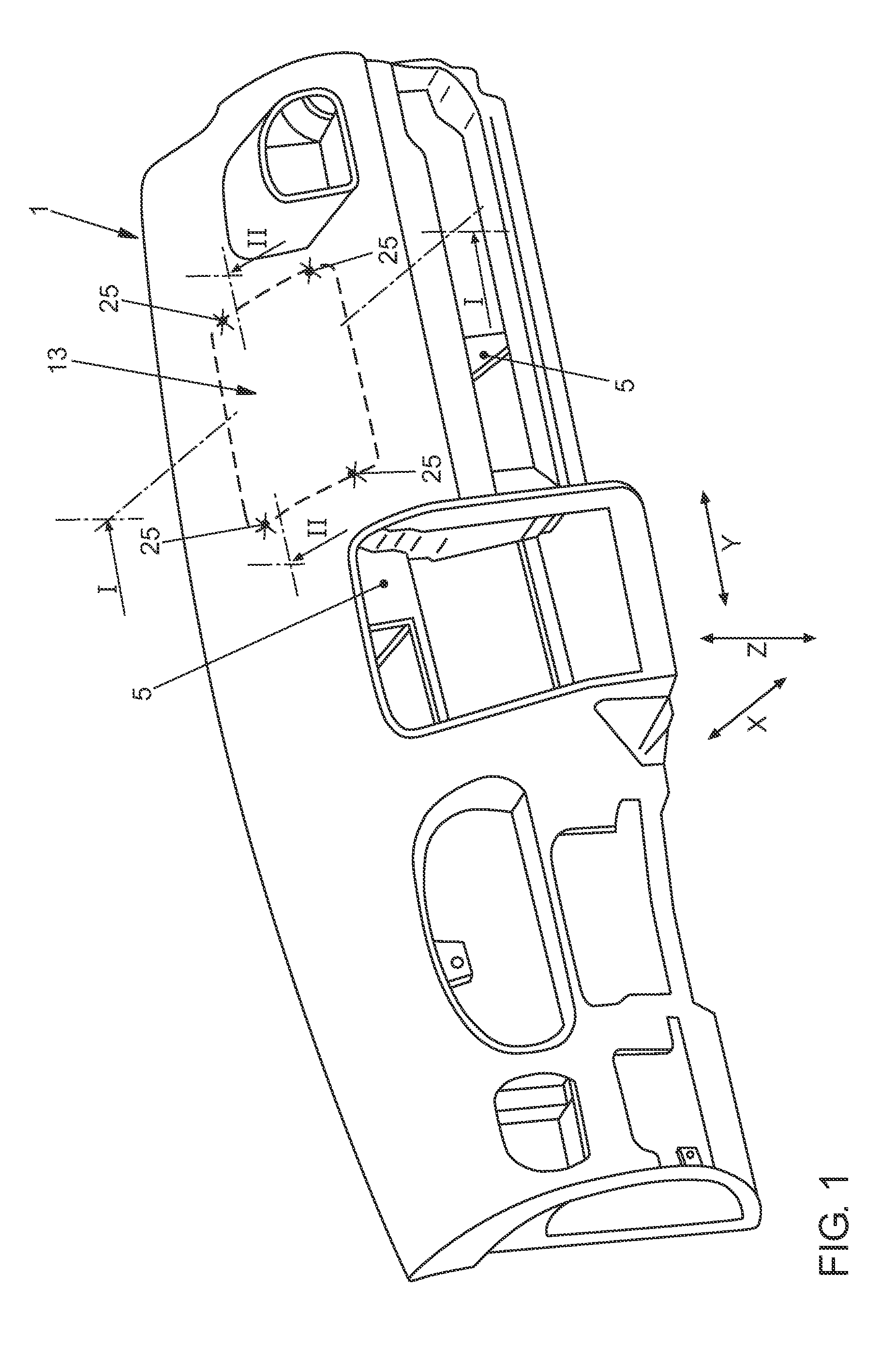
[0026]FIG. 1 shows an instrument panel 1 in a perspective, unique view without the equipped functional elements, that is, without the speedometer, air vent, glove box, radio or similar. In the assembled state, the instrument panel 1 is mounted on a transverse mounting bar 3 (FIG. 2) which extends between the upper A-pillar node of a vehicle body.

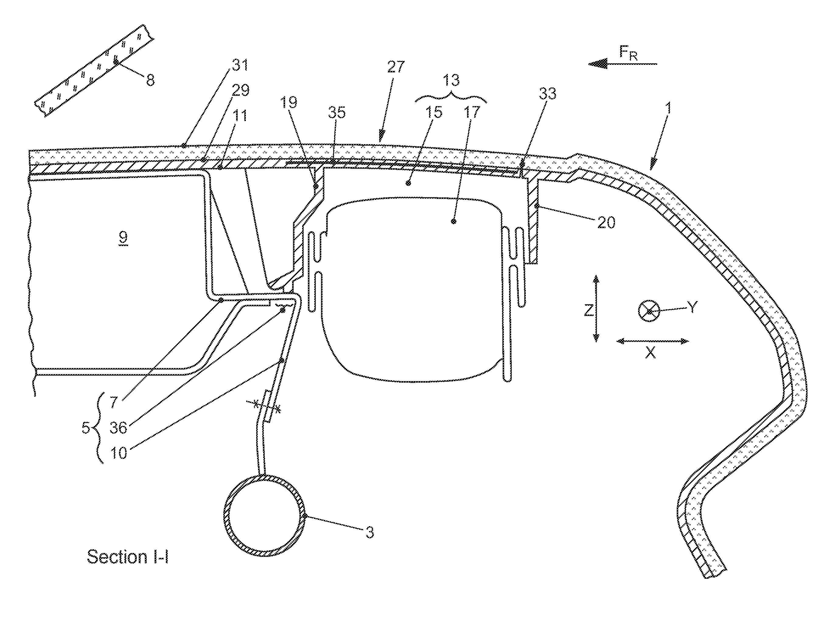
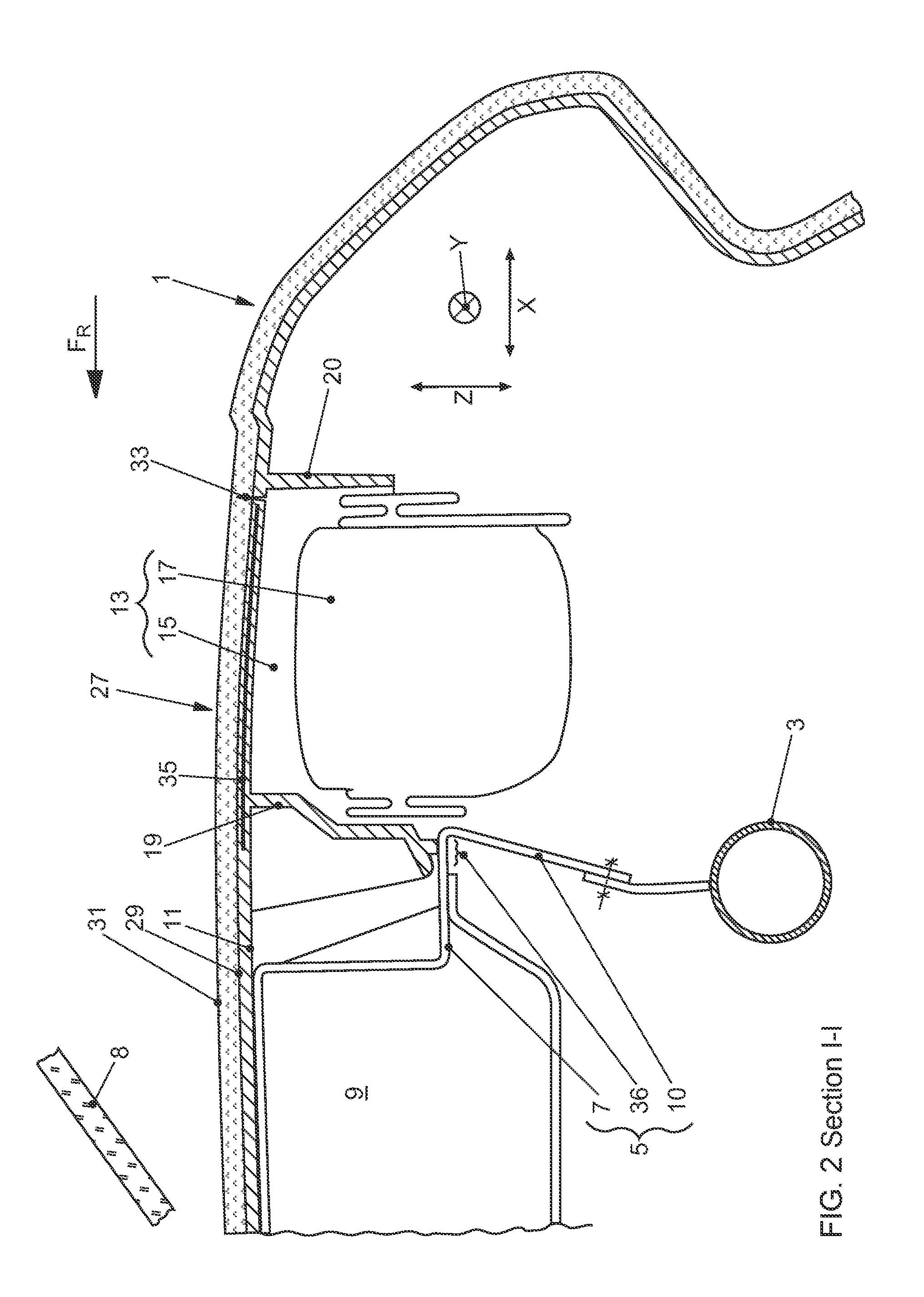
[0027]FIG. 2 shows an assembled state in which the instrument panel 1 is mounted above a frame-like basic body 5 on the transverse mounting bar 3. The basic body 5 has among other things receptacles for the abovementioned functional elements of the instrument panel 1. In addition, the basic body 5 defines air channels of the vehicle ventilation system with delimiting walls 7, that is, in an exemplary manner in FIG. 2, a defrost channel 9 running in the transverse direction of the vehicle y along the windshield 8. This channel is delimited by the delimiting wall 7 and an instrument panel upper part 11 on the visible side. The instrument panel...


PUM


Abstract

An instrument panel for a vehicle, having an instrument panel upper part and a frame-like basic body, which can be mounted on a transverse mounting bar of the vehicle body, which basic body has receptacles for equipping with functional elements, for example radio, glove box, etc., and delimits at least one air channel of a vehicle ventilation system, in particular a defrost channel extending in the transverse direction of the vehicle along the windshield, wherein on the passenger side of the instrument panel an airbag arrangement is integrated which has a firing channel reaching to the instrument panel upper part and an airbag module mounted on a firing channel wall. According to the invention the basic body has at least one supporting section on which the firing channel wall is supported.

Description

[0001]This nonprovisional application is a continuation of International Application No. PCT / EP2014 / 062732, which was filed on Jun. 17, 2014, and which claims priority to German Patent Application No. 10 2013 213 791.5, which was filed in Germany on Jul. 15, 2013, and which are both herein incorporated by reference.BACKGROUND OF THE INVENTION[0002]1. Field of the Invention[0003]The invention relates to an instrument panel for a vehicle.[0004]2. Description of the Background Art[0005]An an instrument panel is typically mounted on a transverse mounting bar which extends in a transverse direction of a vehicle between opposing A-pillar gussets of a vehicle body.[0006]From DE 10 2009 058 688 A1, which is incorporated herein by reference, a class-specific instrument panel for a vehicle is known. This has an instrument panel upper part, having an airbag assembly integrated on the passenger side. The airbag assembly has a frame-shaped firing channel wall delimiting the firing channel. The f...

Claims


Application Information

Patent Timeline
Patent Type & Authority Applications(United States)
IPC IPC(8): B60R21/205B60K37/02B60H1/00B60R11/02B60R7/06B60K37/04
CPCB60R21/205B60R7/06B60K37/04B60R2021/0032B60R11/0205B60K37/02B60H1/00564B60R13/0256B60K35/00B60K2370/658
Inventor KNAUF, RONNYREHMKE, THOMAS
Owner VOLKSWAGEN AG
Why Eureka
Try Eureka