Exhaust gas aftertreatment device with injection section

a technology of exhaust gas aftertreatment and injection section, which is applied in the direction of machines/engines, separation processes, lighting and heating apparatus, etc., can solve the problems of as much as possible mixing-through of evaporated reduction agents and exhaust gas flow, and achieve efficient evaporation effect

Active Publication Date: 2016-05-12
PUREM GMBH
View PDF6 Cites 33 Cited by
  • Summary
  • Abstract
  • Description
  • Claims
  • Application Information

AI Technical Summary

Benefits of technology

[0007]The present invention deals with the problem of providing an improved embodiment for an injection section of the type mentioned above with respect to an exhaust gas aftertreatment device equipped with such, which is characterized in particular by efficient mixing-through for the injected fluid with the exhaust gas flow and which is additionally characterized by an efficient evaporation effect, provided the injected fluid is a liquid.

Problems solved by technology

On the other hand, as intensive as possible a mixing-through of the evaporated reduction agent with the exhaust gas flow also has to be achieved.

Method used


Image

  • Exhaust gas aftertreatment device with injection section
  • Exhaust gas aftertreatment device with injection section
  • Exhaust gas aftertreatment device with injection section

Examples


Embodiment Construction

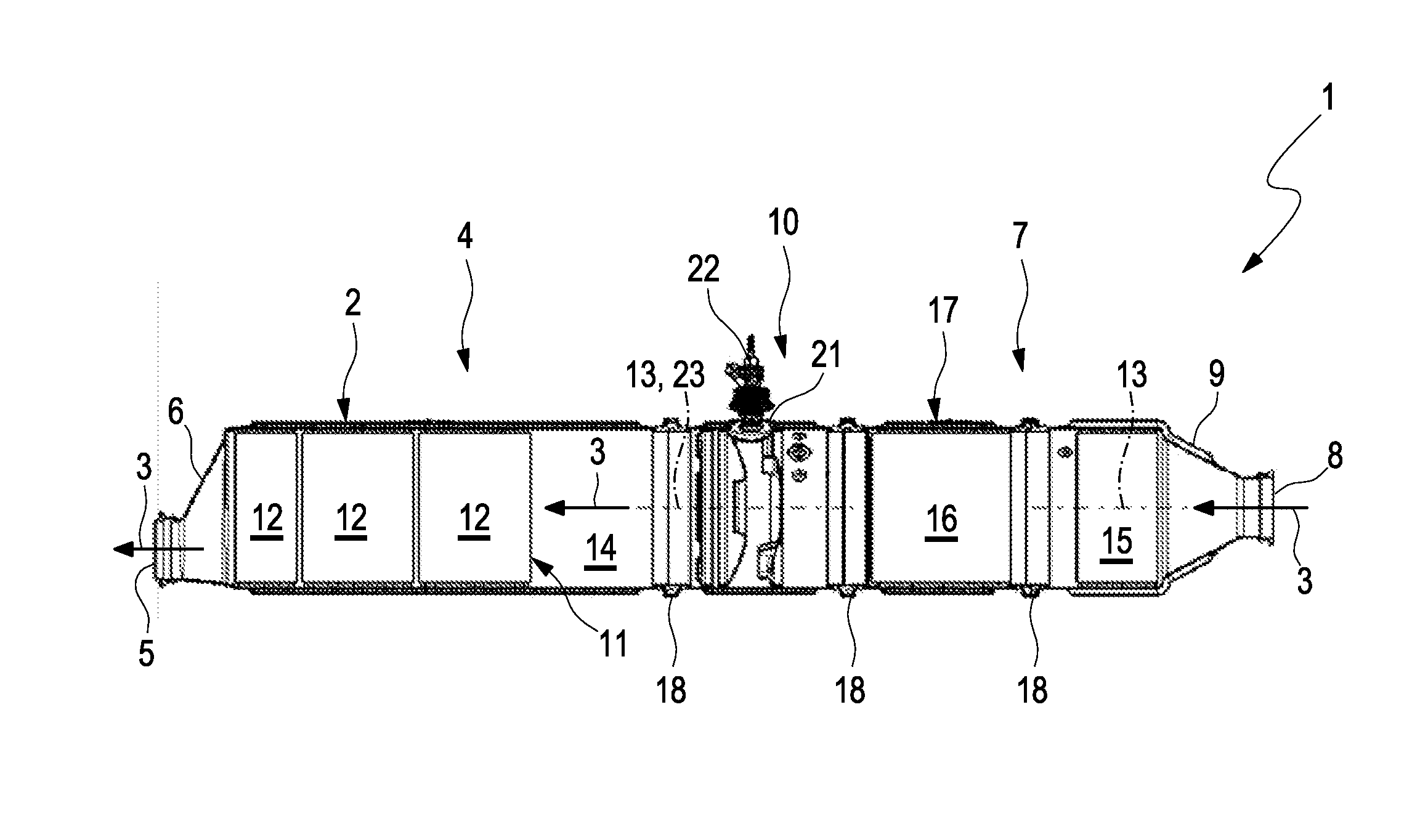
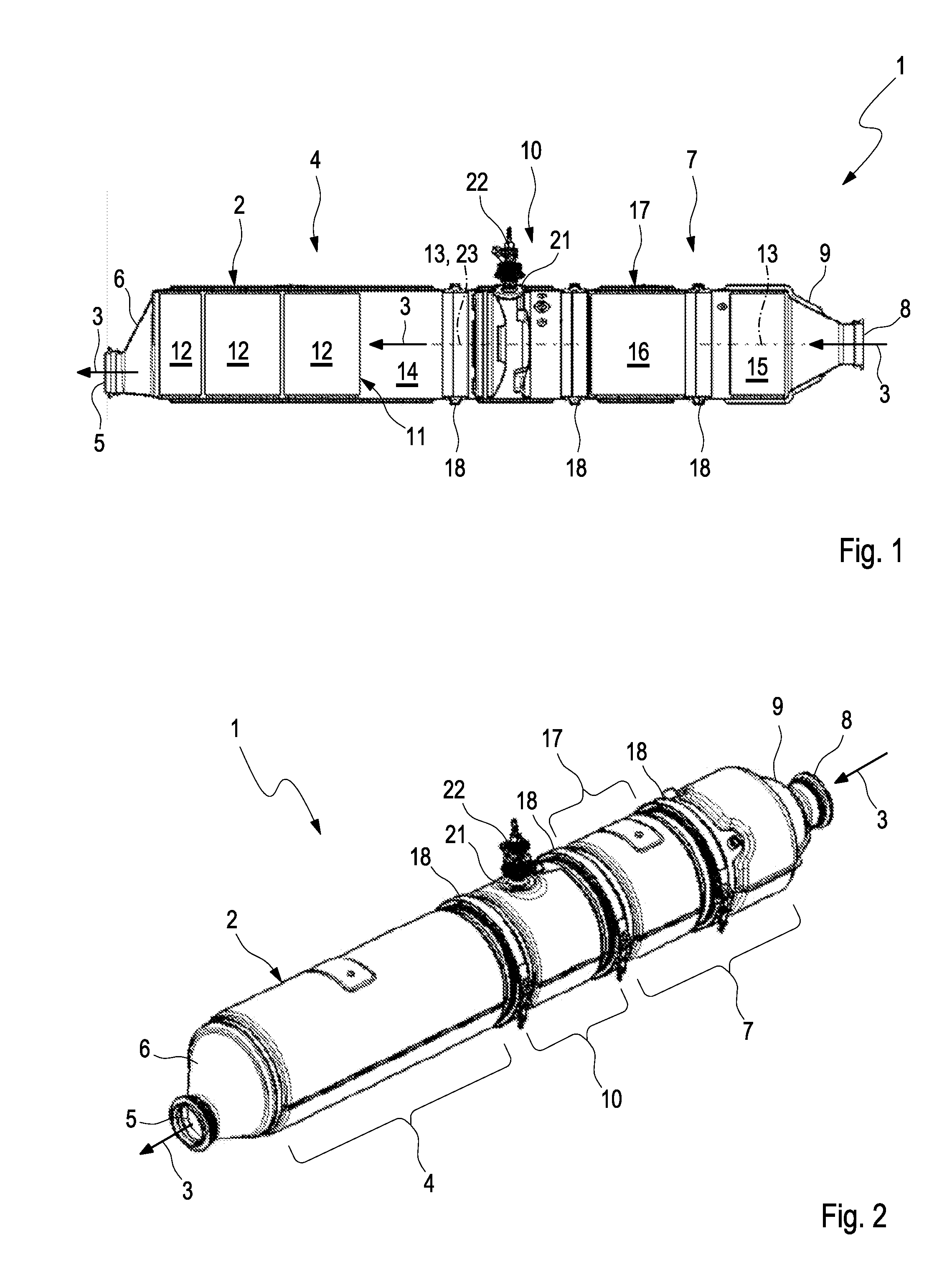
[0049]Referring to the drawings, according to FIGS. 1 and 2, an exhaust gas aftertreatment device 1, which is suitable for use in an exhaust system of an internal combustion engine, comprises a tubular housing 2 for conducting an exhaust gas flow 3 indicated by arrows. The housing 2 in this case comprises an outlet section 4, which comprises an outlet 5 on an outlet funnel 6, and an inlet section 7, which comprises an inlet 8 on an inlet funnel 9. Between inlet section 7 and outlet section 4 an injection section 10 is arranged, which will still be explained in more detail in the following and which serves for introducing a fluid, that is a liquid or a gas, into the exhaust gas flow 3. With respect to the flow direction of the exhaust gas flow 3, the injection section 10 is arranged between the outlet section 4 and the inlet section 7. In the outlet section 4, an SCR-catalytic converter 11 is arranged, which in the example of FIG. 1 comprises three SCR-elements 12 arranged axially on...


PUM

PropertyMeasurementUnit
axial distanceaaaaaaaaaa
volume flow rateaaaaaaaaaa
lengthaaaaaaaaaa

Abstract

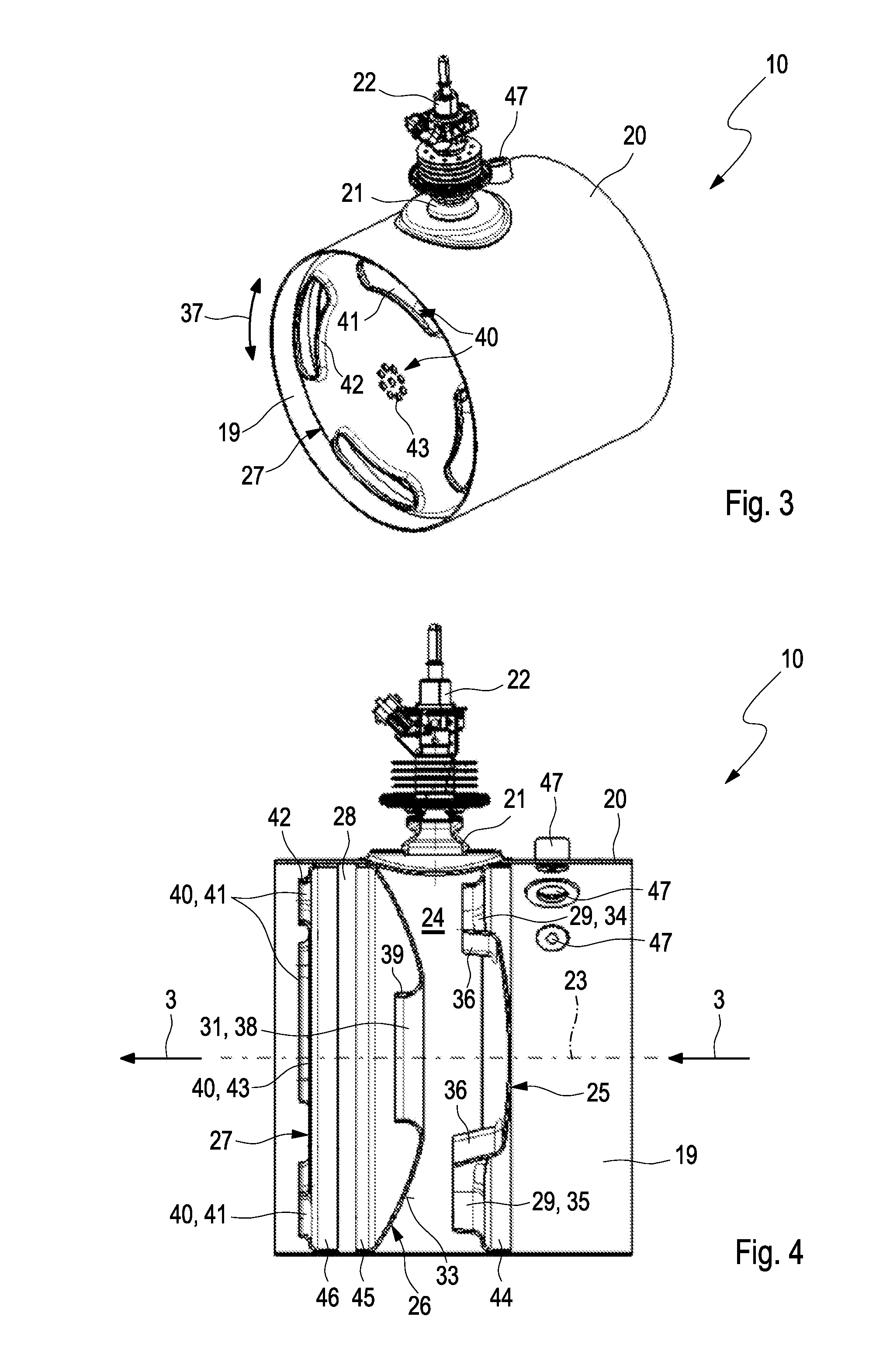
An exhaust system injection section (10) includes an exhaust gas flow channel (19), a laterally arranged injector connection (21), with a fluid introducing injector (22) and an injection chamber (24) formed in the channel, which is delimited by a perforated first separating wall (25), arranged in the channel upstream of the injector connection, and a perforated second separating wall (26) arranged in the channel downstream of the injector connection. To provides intensive mixing of the injected fluid with the exhaust gas flow a perforation (29) of the first separating wall (25) is configured so that exhaust gas largely flows eccentrically through the first separating wall (25) with respect to a longitudinal center axis (23) of the channel and a perforation (31) of the second separating wall (26) is configured so that exhaust gas largely flows concentrically through the second separating wall (26) with respect to the longitudinal center axis (23).

Description

CROSS REFERENCE TO RELATED APPLICATIONS[0001]This application claims the benefit of priority under 35 U.S.C. §119 of German Patent Application 10 2014 222 698.8 filed Nov. 6, 2014, the entire contents of which are incorporated herein by reference.FIELD OF THE INVENTION[0002]The present invention relates to an injection section of an exhaust system for an internal combustion engine with a channel for conducting an exhaust gas flow, an injector connection arranged laterally on the channel, on which an injector for introducing a fluid into the exhaust gas flow can be connected and an injection chamber formed in the channel in the region of the injector connection, which on one side is delimited by a perforated separating wall through which exhaust gas can flow and which with respect to the exhaust gas flow is arranged in the channel upstream of the injector connection and on the other side by a perforated second separating wall through which exhaust gas can flow and which with respect ...

Claims


Application Information

Patent Timeline
Patent Type & Authority Applications(United States)
IPC IPC(8): F01N3/20B01D53/94F01N3/28
CPCF01N3/2066F01N3/2892F01N2610/1453B01D53/9431F01N2610/02B01D53/9418F01N3/28F01N2490/00F01N3/103F01N3/021F01N2240/20F01N13/0097F01N13/0093F01N13/008Y02T10/12B01F23/2132B01F25/3141B01F25/4233
Inventor KAUDERER, ALEXANDERWOLF, TOBIASKARELIN, KIRILL
Owner PUREM GMBH
Why Eureka
Try Eureka