Air conditioning device

a technology for air conditioning devices and filters, applied in the field of air conditioning devices, can solve the problems of increased manufacturing cost of products, increased space requirements, and increased manufacturing costs of products, and achieve the effect of reducing the number of filters required and reducing the manufacturing cost of air conditioning devices

Inactive Publication Date: 2016-05-12
SAMSUNG ELECTRONICS CO LTD
View PDF1 Cites 6 Cited by
  • Summary
  • Abstract
  • Description
  • Claims
  • Application Information

AI Technical Summary

Benefits of technology

[0009]The present disclosure has been made to address at least the above problems and / or disadvantages and to provide at least the advantages described below. Accordingly, an aspect of the present disclosure provides an air conditioning device, which can reduce the number of filters required and thus can reduce the manufacturing cost of the air conditioning device by designing a flow path so that an outdoor air inlet port and an indoor air inlet port can be constantly maintained even if the performing function of the air conditioning device is modified.

Problems solved by technology

However, this may cause inconvenience.
However, if a plurality of indoor air inlet ports are provided, it becomes necessary to install separate ducts for the respective indoor air inlet ports, and thus the manufacturing cost is increased.
Further, additional space is required in installing the air conditioning device, and a plurality of ducts should be connected to the air conditioning device which causes inconvenience.
Accordingly, in the case where the outdoor air inlet port and the outdoor air discharge port are modified to match the case where they perform their own functions, it is required to install additional filters for filtering pollution materials from external air on the outdoor air inlet port and the outdoor air discharge port, and this causes the manufacturing cost of the product to be increased.

Method used


Image

  • Air conditioning device
  • Air conditioning device
  • Air conditioning device

Examples


Embodiment Construction

[0037]Hereinafter, an air conditioning device 1 according to an embodiment of the present disclosure will be described with reference to the accompanying drawings. In describing the embodiment of the present disclosure, a detailed description of known constructions or functions will be omitted if it is deemed that such description would make the gist of the present disclosure unnecessarily vague. In the drawings, to help the understanding of the present disclosure, sizes of some constituent elements may be exaggerated for clarity in explanation.

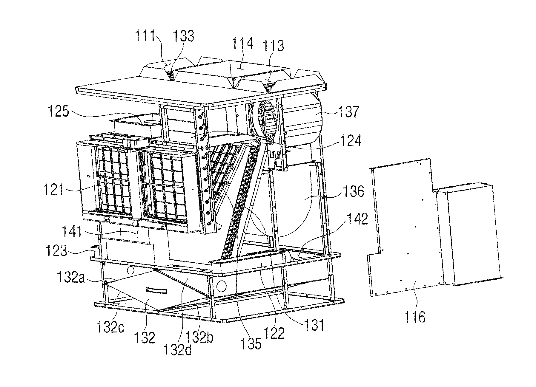
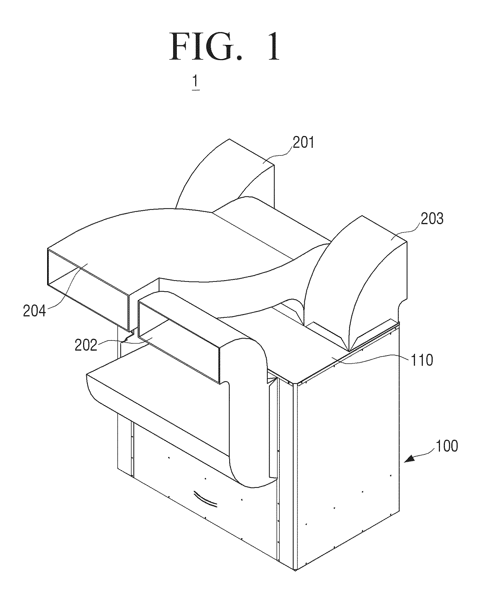
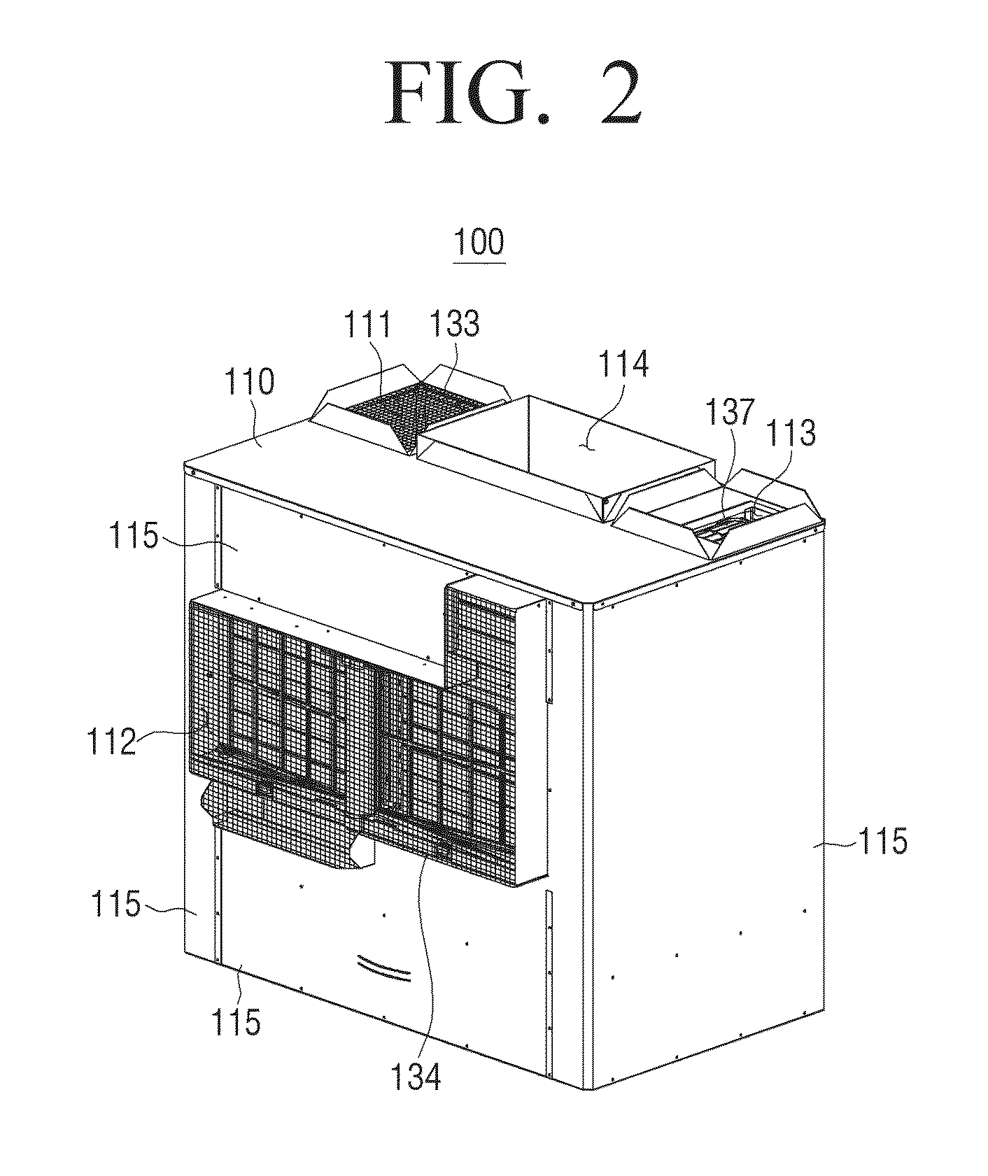
[0038]FIG. 1 is a perspective view illustrating an air conditioning device 1 according to an embodiment of the present disclosure, and FIG. 2 is a perspective view illustrating the shape of a main body portion 100 from which first to fourth ducts 201 to 204 are separated in the air conditioning device 1 of FIG. 1. FIGS. 3 and 4 are exploded perspective views illustrating the main body portion 100 of FIG. 2, from which external covers 115 and ...


PUM


Abstract

An air conditioning device having an indoor heat exchanger, a heat recovery ventilator, a supply fan, and an exhaust fan inside a housing and configured to perform at least one of cooling/heating, heat recovery ventilation, and pure ventilation. The air conditioning device includes a first flow path configured to guide indoor air while the cooling/heating is performed, a second flow path configured to guide the indoor air toward the heat recovery ventilator, and a third flow path configured to guide outdoor air toward the heat recovery ventilator while the heat recovery ventilation is performed. The air conditioning device includes fourth and fifth flow paths configured to guide indoor air and outdoor air, respectively, and an inlet port that corresponds to the third flow path and the fifth flow path, and a discharge port that corresponds to outlets of the second flow path and the fourth flow path.

Description

CROSS-REFERENCE TO RELATED APPLICATIONS[0001]This application claims priority under 35 U.S.C. §119(a) to Korean Patent Application No. 10-2014-0157354, filed on Nov. 12, 2014, in the Korean Intellectual Property Office, the disclosure of which is incorporated herein by reference.BACKGROUND[0002]1. Field[0003]The present disclosure relates generally to an air conditioning device, and more particularly to an air conditioning device, which can simultaneously perform ventilation and cooling / heating.[0004]2. Description of the Related Art[0005]Recently, the moderns make a living indoors, such as inside a building or a means of transportation, most of the day. In order to keep the interior of a room in an agreeable environment, a window may be opened for ventilation, or a separate ventilation device may be installed. However, this may cause inconvenience.[0006]In order to solve the above-described problem, various air conditioning devices having ventilation functions have recently been pr...

Claims


Application Information

Patent Timeline
Patent Type & Authority Applications(United States)
IPC IPC(8): F24F11/00F24F13/02F24F7/08F24F12/00
CPCF24F11/0001F24F12/001F24F2011/0002F24F7/08F24F13/02F24F1/00F24F1/0003F24F1/0007F24F12/006F24F13/30F24F3/044Y02B30/56Y02B30/70F24F13/28F24F11/30F24F11/65F24F1/0035F24F1/0041F24F1/0073
Inventor LEE, JE-GUNA, SEON-UKTAE, SANG-JIN
Owner SAMSUNG ELECTRONICS CO LTD
Why Eureka
Try Eureka