
Method and apparatus of networked thermostats providing for reduced peak power demand

Inactive Publication Date: 2016-05-12
VERDANT ENVIRONMENTAL TECH INC
View PDF30 Cites 22 Cited by
  • Summary
  • Abstract
  • Description
  • Claims
  • Application Information

AI Technical Summary

Benefits of technology

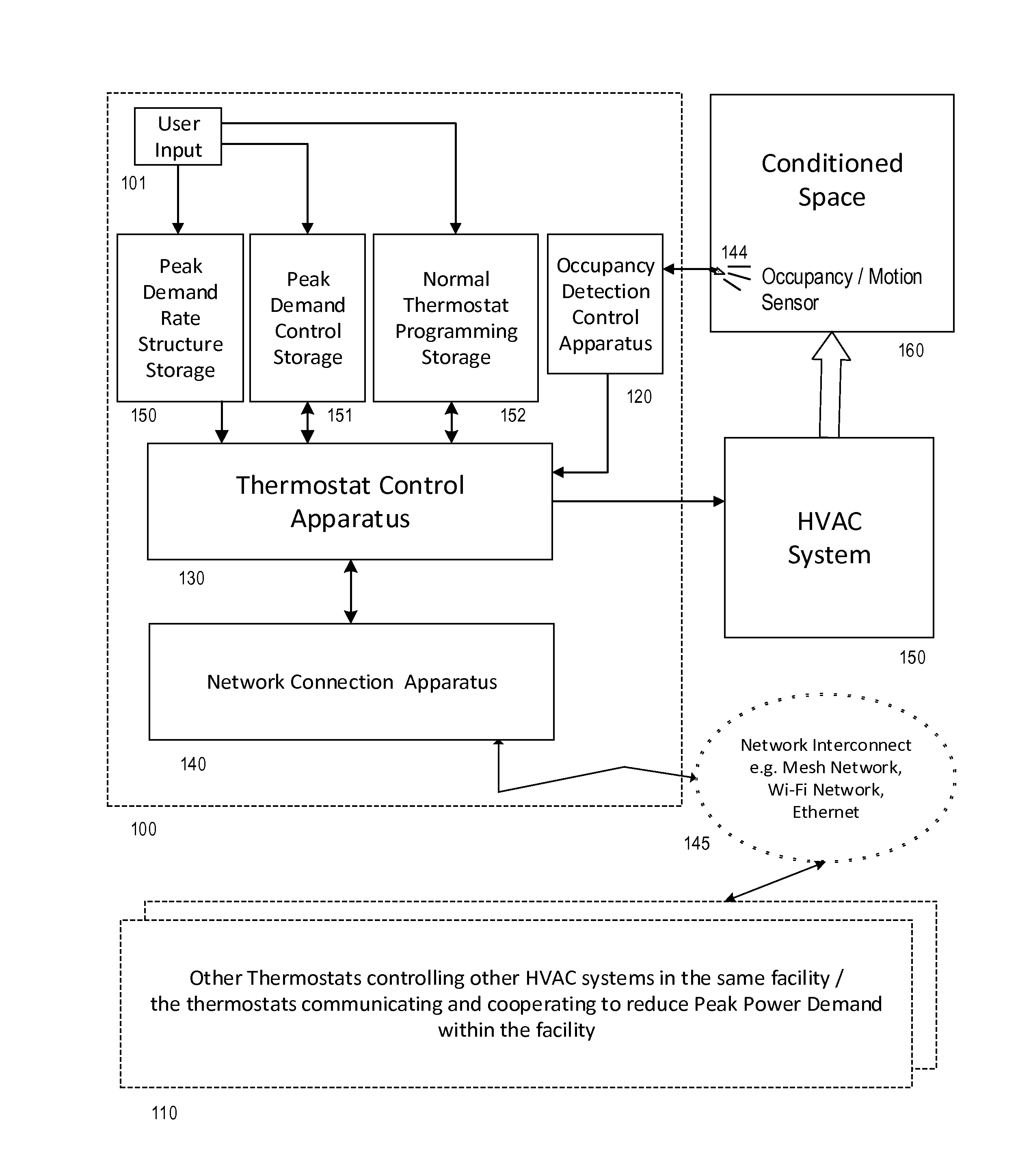
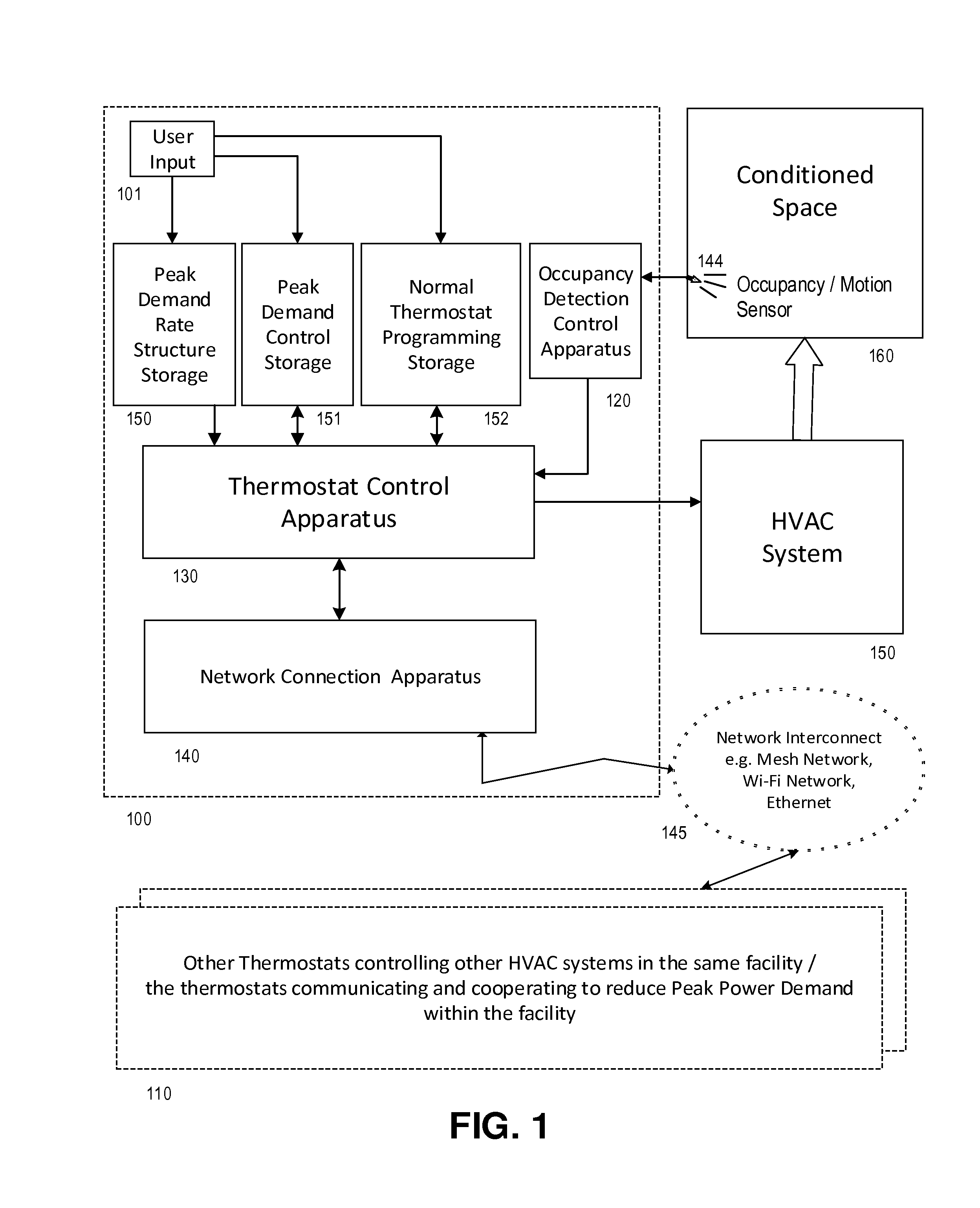
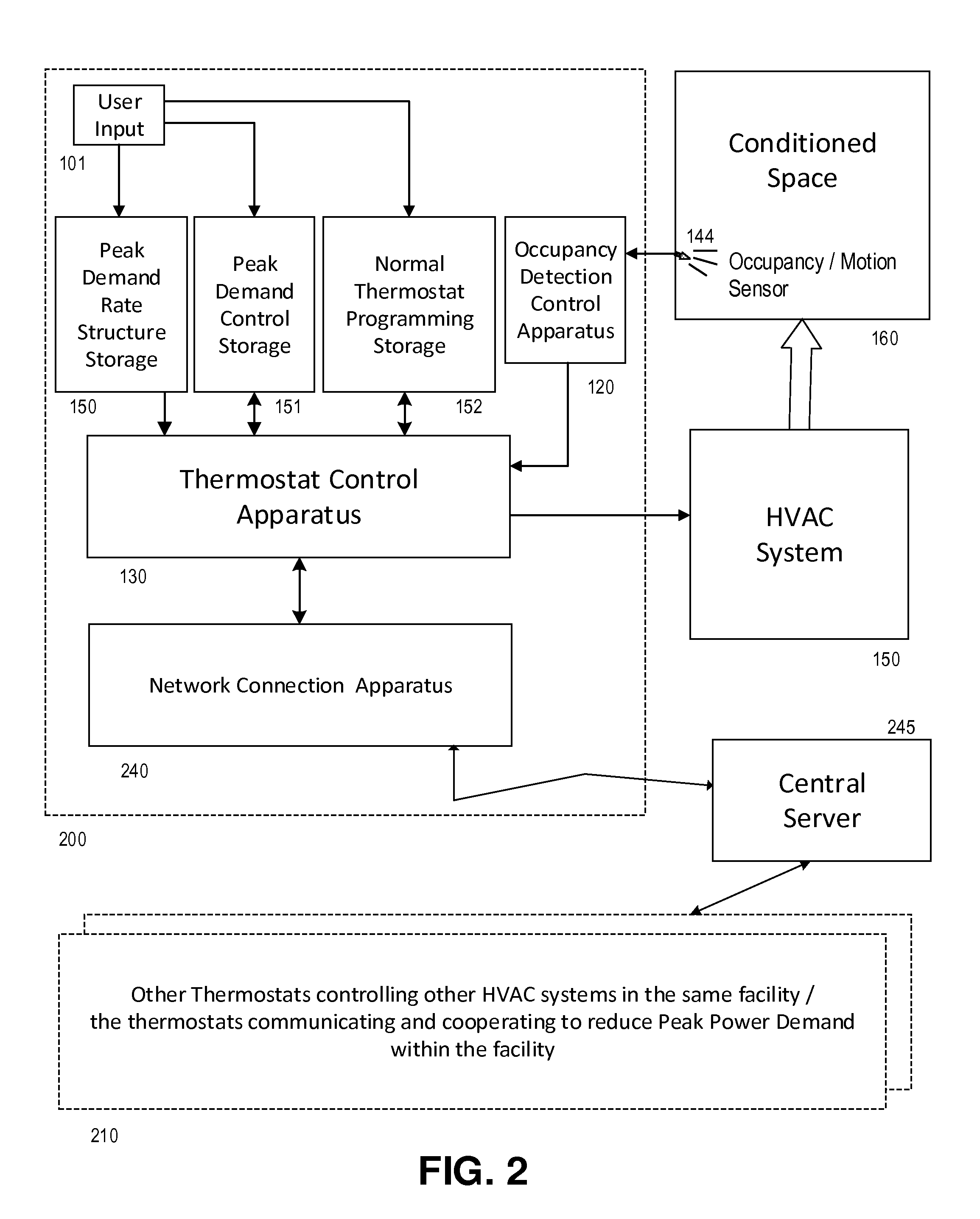
The patent is about controlling multiple HVAC systems using thermostats that are connected to a network. The goal is to reduce peak power demand, which can lower energy costs. The control system should also be based on specific rules set forth by the power company, and can optionally use GPS or other location information to determine which power company to control. The system can also automatically select the appropriate demand rate structure based on the power company's rules and algorithm changes based on season or date. The patent also mentions the option of automated communication with a central server that stores information about demand rate structures and further enables users to select specific structures.

Problems solved by technology

When a plurality of thermostats are used to control a corresponding plurality of Heating, Cooling, and / or Ventilation Systems (HVAC Systems) it may happen that turning on a number of HVAC systems results at the same time or over a short period of time may result in a high “peak demand” in usage of electrical power.
High peak power demands are often deemed as detrimental by power companies supplying power to an end user and there are often charges associated with high peak power demand.

Method used


Image

  • Method and apparatus of networked thermostats providing for reduced peak power demand
  • Method and apparatus of networked thermostats providing for reduced peak power demand
  • Method and apparatus of networked thermostats providing for reduced peak power demand

Examples


Embodiment Construction

[0043]The following detailed description includes references to the accompanying figures of the drawing, which form a part of the detailed description. The figures show, by way of illustration, specific embodiments in which the apparatus may be practiced. These embodiments, which are also referred to herein as “examples” or “options,” are described in enough detail to enable those skilled in the art to practice the illustrated embodiments. The disclosed embodiments may be combined, other embodiments may be utilized or structural or logical changes may be made without departing from the scope of the invention. The following detailed description is, therefore, not to be taken in a limiting sense and the scope of the invention is defined by the appended claims and their legal equivalents.

[0044]The present invention as described and / or illustrated according to the embodiments discussed above is directed to an improved method and system for managing a network of thermostats that overcome...


PUM


Abstract

An improvement in operation of a network of thermostats is disclosed which reduces peak power demand requirements for a facility that utilizes a plurality of heating, ventilation and cooling systems controlled by the thermostats or by a central control system utilizing status data from a plurality of thermostats.

Description

FIELD OF USE[0001]This invention relates to the art of environmental control systems, to thermostats which control heating, ventilation and cooling systems, and in particular to thermostats which are connected in a network to other thermostats or to a central control system.[0002]Further optional aspects of the invention relate to thermostats which include occupancy sensors or motion sensors for detecting occupancy within a conditioned space and optionally including detecting and / or recording patterns of occupancy within a conditioned space.BACKGROUND OF THE INVENTION[0003]Occupancy detection and / or patterns of occupancy are optionally utilized by certain thermostats to reduce overall electrical power consumption in the heating, cooling, or ventilation of a room or conditioned space. When a plurality of thermostats are used to control a corresponding plurality of Heating, Cooling, and / or Ventilation Systems (HVAC Systems) it may happen that turning on a number of HVAC systems result...

Claims


Application Information

Patent Timeline
IPC IPC(8): F24F11/00G05B15/02F24F11/02
CPCF24F11/006F24F11/0012F24F11/0034F24F11/02F24F2011/0075F24F2011/0047F24F2011/0063F24F2011/0071G05B15/02G05B2219/2614F24F11/30F24F2120/10F24F2140/60F24F11/62F24F11/64F24F11/46F24F11/58F24F2120/00F24F11/47F24F11/54
Inventor ROSEN, HOWARD
Owner VERDANT ENVIRONMENTAL TECH INC
Learn More