
Method for operating a local energy network

a local energy network and energy network technology, applied in non-electric variable control, process and machine control, instruments, etc., can solve the problems of increasing energy costs, high cost of charging devices, and unlikely use in private households, so as to avoid overloading of building connection technology, increase energy costs, and avoid overloading

Inactive Publication Date: 2013-11-14
ROBERT BOSCH GMBH
View PDF19 Cites 2 Cited by
  • Summary
  • Abstract
  • Description
  • Claims
  • Application Information

AI Technical Summary

Benefits of technology

The patent is about a system that helps manage the charging and discharging of electric vehicles, taking into account factors like cost, CO2 emissions, charging speed, network utilization, battery status, or frequency of use. The system makes use of physical boundaries and prevents overloading of the building or household connection. It optimizes energy efficiency, provides economical usage for network operators, and reduces the need for additional network capacity. The system also enables participation in the balancing energy market, allowing the vehicle to earn income and avoiding network expansion. Additionally, the system improves the quality of the supply network and compensates for local power bottlenecks, ensuring smooth operation for the end user. Overall, the system helps minimize energy costs and optimizes the use of electric vehicles.

Problems solved by technology

This is problematic in particular during periods of time in which a peak load is demanded.
This problem is exacerbated by the increasing number of electric loads.
However, the charging devices required for this are very expensive, so that at this time their use in private households appears unlikely.
This prevents the vehicle owner from being able to carry out a charging and discharging of the vehicle battery in accordance with his wishes.
However, in the future this will no longer be acceptable.

Method used


Image

  • Method for operating a local energy network
  • Method for operating a local energy network
  • Method for operating a local energy network

Examples


Embodiment Construction

[0027]The present invention is schematically shown on the basis of specific embodiments in the drawings, and is explained in detail below with reference to the drawings.

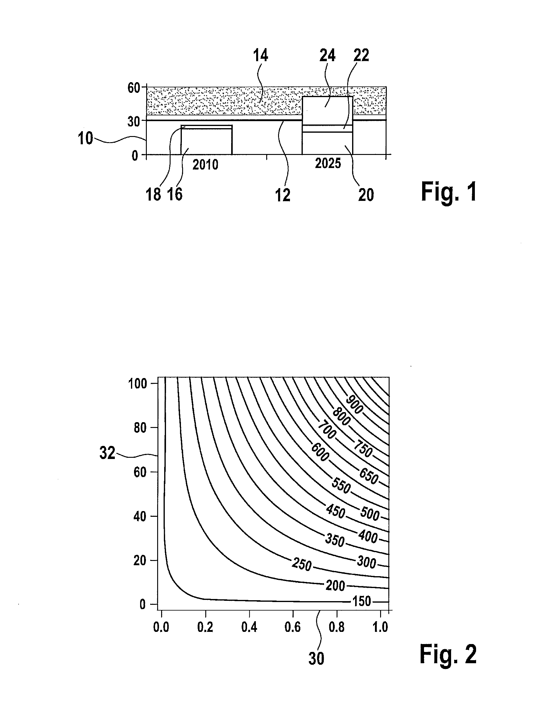
[0028]FIG. 1 shows an overload in a household connection. In the drawing, electrical power in kW is plotted on an ordinate 10. A threshold 12 is plotted at 30 kW; beyond this is an overload region 14 of the household connection. The drawing shows, for the year 2010, the power requirements and thus the energy requirements of the loads in the house, which in this case represents the local energy network. A first clock 16 indicates the power requirements of the household devices, and a second black 18 indicates the requirements for heating and air conditioning. The drawing shows that the power requirements in the house as a whole remain below threshold 12.

[0029]A corresponding division of the energy requirements is also plotted for the year 2025. Again, a first block 20 is shown for the requirements of the household dev...


PUM


Abstract

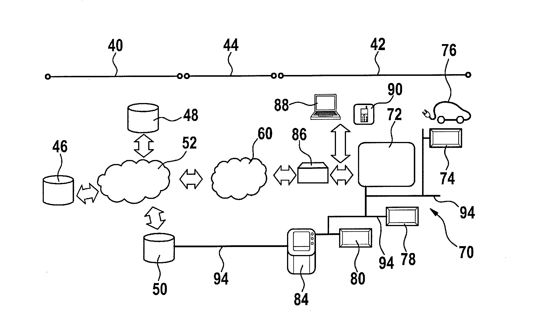
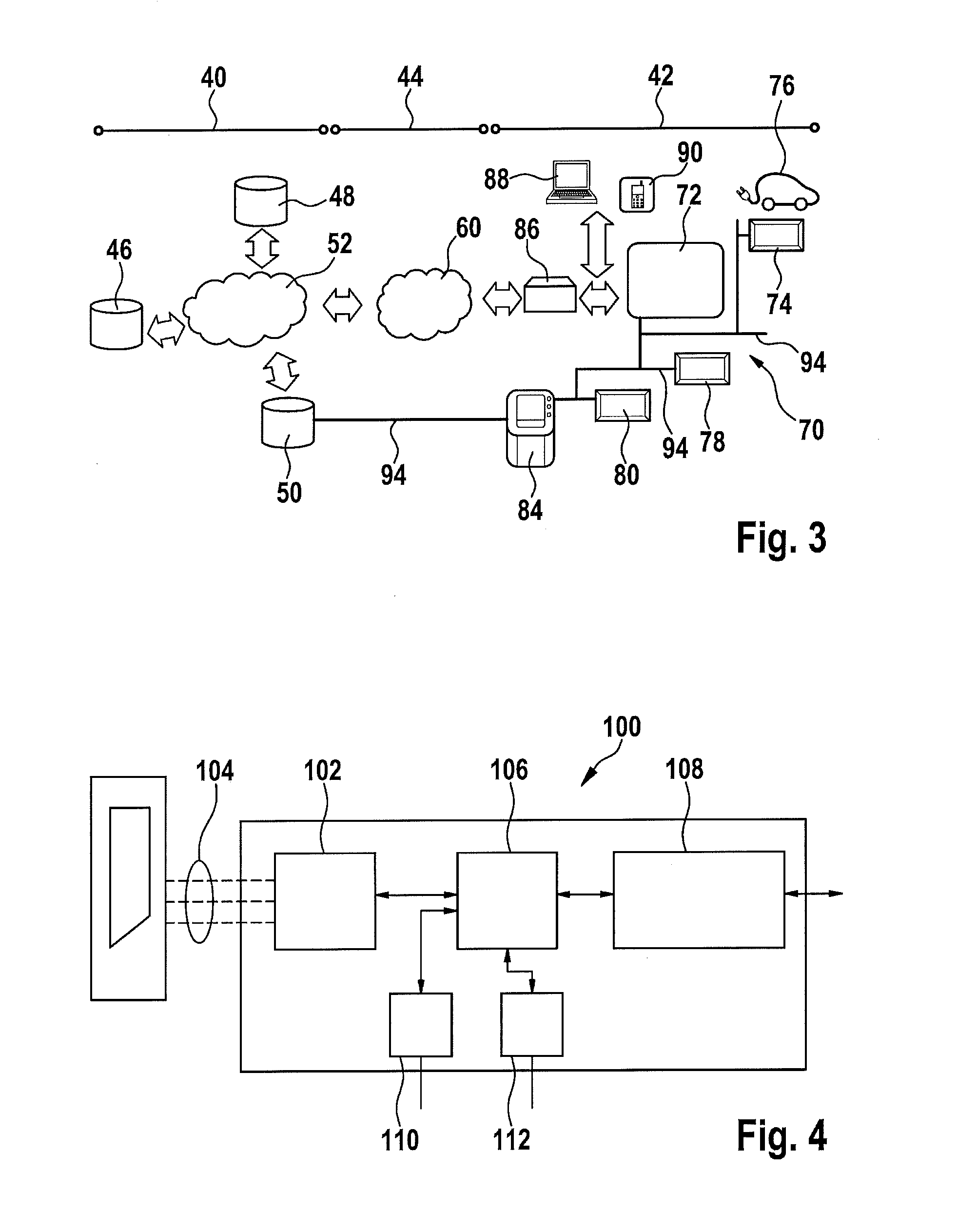
A method and a system are presented for operating a local energy network that has a limited network utilization and in which a plurality of loads can be connected via a power network. An energy requirement of each load is detected, and an allocation of the available energy to the loads takes place as a function of a maximum utilization of the energy network. At the same time, communication is enabled.

Description

FIELD OF THE INVENTION[0001]The present invention relates to a method for operating a local energy network and to a system for carrying out the method.BACKGROUND INFORMATION[0002]Local energy networks include a number of loads whose energy requirement has to be ensured in the network in order to ensure the functional capacity of the network as a whole. Thus, for example in private households it should be ensured that sufficient energy, generally electric energy, is available at all times. Here it is to be noted that in households only a limited quantity of electric power is provided, which is limited for example in houses and buildings via a central main circuit breaker. This is problematic in particular during periods of time in which a peak load is demanded. This problem is exacerbated by the increasing number of electric loads. Here it is to be noted in particular that, increasingly, energy storage devices of electric vehicles are charged via the household network.[0003]All elect...

Claims


Application Information

Patent Timeline
Patent Type & Authority Applications(United States)
IPC IPC(8): H02J4/00
CPCH02J4/00B60L2240/70B60L2260/52Y02B70/3225Y02T90/16Y04S10/126Y04S20/222Y04S20/242Y04S40/124Y02T10/7072B60L53/63H02J2310/14H02J13/00009H02J2310/48H02J2310/60H02J3/322H02J13/00016H02J13/00004H02J13/00028H02J3/14Y02B70/30Y02B90/20Y02E60/00Y02T10/70Y02T10/72Y02T90/12Y04S40/121Y02T90/14
Inventor SCHAUT, JOHANNES-ALEXANDERSCHOEPF, FRIEDRICHBRANDSTETTER, MARKUS
Owner ROBERT BOSCH GMBH
Learn More