Contaminant recovery device

a contaminant recovery and contaminant technology, applied in water contaminants, water/sludge/sewage treatment, sewerage structures, etc., can solve the problems of increasing the energy cost of the end user, the need for contaminant recovery operation to run, and the limited amount of contaminants in the vicinity of skimming means, so as to increase the efficiency of contaminant recovery operation and reduce the time required

Active Publication Date: 2019-09-03
FM ENVIRONMENTAL LTD
View PDF14 Cites 0 Cited by
  • Summary
  • Abstract
  • Description
  • Claims
  • Application Information

AI Technical Summary

Benefits of technology

[0004]It is an object of the present invention to increase the efficiency of a contaminant recovery operation and / or reduce the time required to perform such an operation.
[0006]Advantageously, the means for inducing a flow in at least part of the body of contaminated liquid at or about the skimming means is able to induce a flow and / or flow change in the body of contaminated liquid around the skimming means. This allows for a greater volume of contaminants to be removed during a skimming operation. In existing systems, the contaminant recovery devices rely upon the natural flow and / or drift of liquid, which is often unpredictable, in a direction away from the skimming means. As such, the amount of contaminants in the vicinity of the skimming means is often limited, and the contaminant recovery operation needs to run for a long time in order for the contaminants to slowly drift towards the skimming means. This is both inefficient, and also increases the energy costs for the end user. The present invention induces a flow in the body of contaminated liquid, and so avoids the need to rely upon the natural flow and / or drift of liquid, thereby reducing running times and improving the contaminant recovery devices skimming efficiency.
[0039]Advantageously, the wiper blade assembly is able to remove contaminants from the skimming means, such that the contaminants can be permanently removed from the body of contaminated liquid.
[0050]Advantageously, the inlet baffle acts to slow the flow of the contaminated liquid down which allows and / or accelerates the separation of the contaminants from the liquid. The inlet baffle further acts to redirect the flow downwards which also assists in the separation process.

Problems solved by technology

In existing systems, the contaminant recovery devices rely upon the natural flow and / or drift of liquid, which is often unpredictable, in a direction away from the skimming means.
As such, the amount of contaminants in the vicinity of the skimming means is often limited, and the contaminant recovery operation needs to run for a long time in order for the contaminants to slowly drift towards the skimming means.
This is both inefficient, and also increases the energy costs for the end user.

Method used


Image

  • Contaminant recovery device

Examples


Embodiment Construction

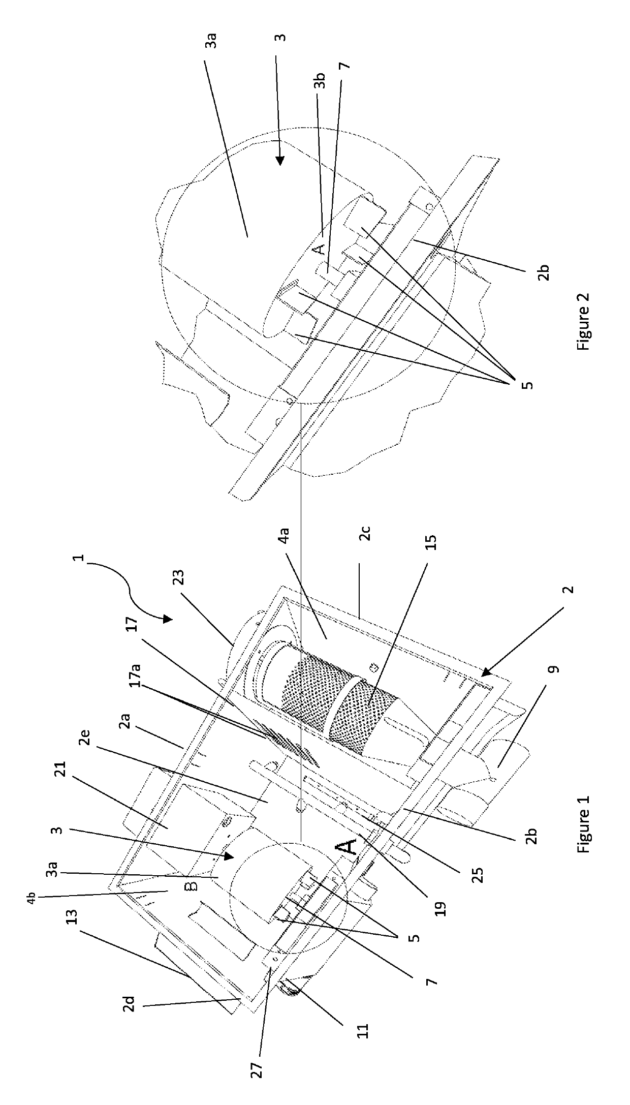
[0068]In FIG. 1, there is shown a contaminant recovery device indicated generally by the reference numeral 1. The contaminant recovery device 1 shown in FIG. 1 is of a type suitable to be positioned underneath a sink space such that the contaminant recovery device 1 can receive contaminated liquid from the sink drain and recover contaminants such as fats, oils and grease therefrom. The skilled person will appreciate that this one example arrangement of the present invention and the present invention is not limited to this specific embodiment. For example, the contaminant recovery device 1 can also be connected to any of pot wash sinks, pre-rinse sinks, combination ovens, Asian woks, and floor drains.

[0069]The contaminant recovery device 1 comprises a container indicated generally by the reference numeral 2 which is sized to retain a body of contaminated liquid. The container 2 of FIG. 1 is a generally rectangular shaped container 2 with a front wall 2a, rear wall 2b, and side walls ...


PUM

PropertyMeasurementUnit
circumferenceaaaaaaaaaa
lengthaaaaaaaaaa
heightaaaaaaaaaa

Abstract

A contaminant recovery device comprising a container sized to hold a body of contaminated liquid. A skimming arrangement adaptable to at least temporarily remove contaminants from the body of contaminated liquid and an assembly for inducing a flow in at least part of the body of contaminated liquid at or about the skimming arrangement. The skimming arrangement is adaptable to at least temporarily remove contaminants from around the surface of the body of contaminated liquid.

Description

CROSS-REFERENCE TO RELATED APPLICATION[0001]The instant application claims priority to United Kingdom Patent Application Serial No. GB1611364.9 filed Jun. 30, 2016, the entire specification of which is expressly incorporated herein by reference.FIELD OF THE INVENTION[0002]The present invention relates to a contaminant recovery device.BACKGROUND OF THE INVENTION[0003]Contaminant recovery devices such as grease recovery devices and / or grease traps are widely used in commercial and residential settings to remove contaminants such as fats, oils and grease from a body of water. In a typical arrangement, the contaminant recovery device will have a liquid storage container with an inlet coupled to a sink drain and an outlet coupled to the wastewater outlet pipe for the building and / or setting where the sink is located. Contaminated liquid will enter the liquid storage container via the inlet where it separates from the water and / or liquid and rises to the surface. A baffle arrangement is p...

Claims


Application Information

Patent Timeline
Patent Type & Authority Patents(United States)
IPC IPC(8): C02F1/40B01D17/032E03F5/16B01D17/02B01D17/00B01D17/12C02F101/32
CPCB01D17/02B01D17/0214B01D17/10B01D17/12E03F5/16C02F1/40C02F2101/32
Inventor ATTARD, CHRISTIANFITZPATRICK, CORMACFARRUGIA, MARIO
Owner FM ENVIRONMENTAL LTD
Why Eureka
Try Eureka