Gooseneck style vent

a gooseneck and vent technology, applied in the field of vents, can solve the problems of metal flapper valves making quite a bit of noise, easy damage in transit, and easy to rust, and achieve the effects of quiet and reliable, simple use, and easy installation

Active Publication Date: 2016-05-12
CANPLAS INDS
View PDF10 Cites 14 Cited by
  • Summary
  • Abstract
  • Description
  • Claims
  • Application Information

AI Technical Summary

Benefits of technology

[0007]What is desired is a simple to use, inexpensive, easy to install, and aesthetically pleasing vent that will allow air to escape when it is desired and yet will protect the vent from unwanted opening and closing of the flapper valve. Such a design would preferably be quiet and reliable and should also prevent unwanted pests and the like from intruding into the building through the vent. Such a vent would preferably respond to the need to vent air, but would otherwise be reliably closed to prevent the infiltration of weather and outside air.
[0008]The present invention provides in a preferred embodiment a form of an inexpensive and yet durable vent. The vent may be formed from a flexible material such as sheet metal or molded plastic, such as polypropylene, which is durable and not easily damaged. Such a plastic vent will preferably have a flapper valve that opens and closes silently as compared to the prior art metal devices. The vent may include a built-in screen to limit weather and pests from impinging on the flapper valve or getting into the building through the vent. Most preferably the vent can be comprised of a number of separate elements that are easily molded and which can be easily assembled to form a complete vent structure having certain desirable features as explained below.

Problems solved by technology

Various designs have been proposed in the past including vents made from metal, but these tend to be expensive and easily damaged in transit.
Further a metal flapper valve can make quite a bit of noise when it opens and closes.
A problem with prior art designs is that wind or weather can change the air pressure around the exterior of the vent causing the flapper to flap up and down even when the inside appliance is not turned on and there is no need for the vent to be open.
This constant chatter can become a serious issue to an occupant.

Method used


Image

  • Gooseneck style vent
  • Gooseneck style vent
  • Gooseneck style vent

Examples


Embodiment Construction

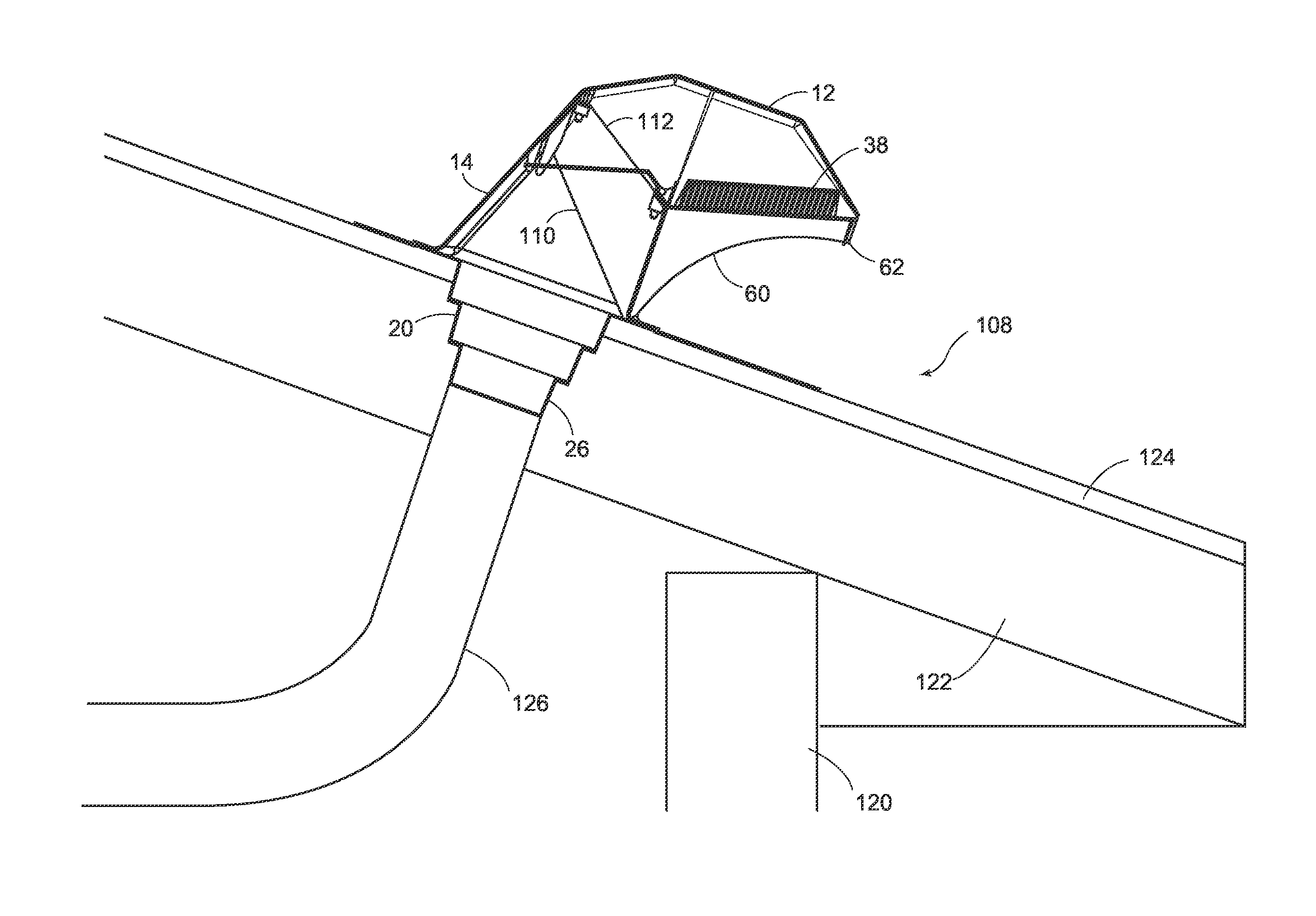
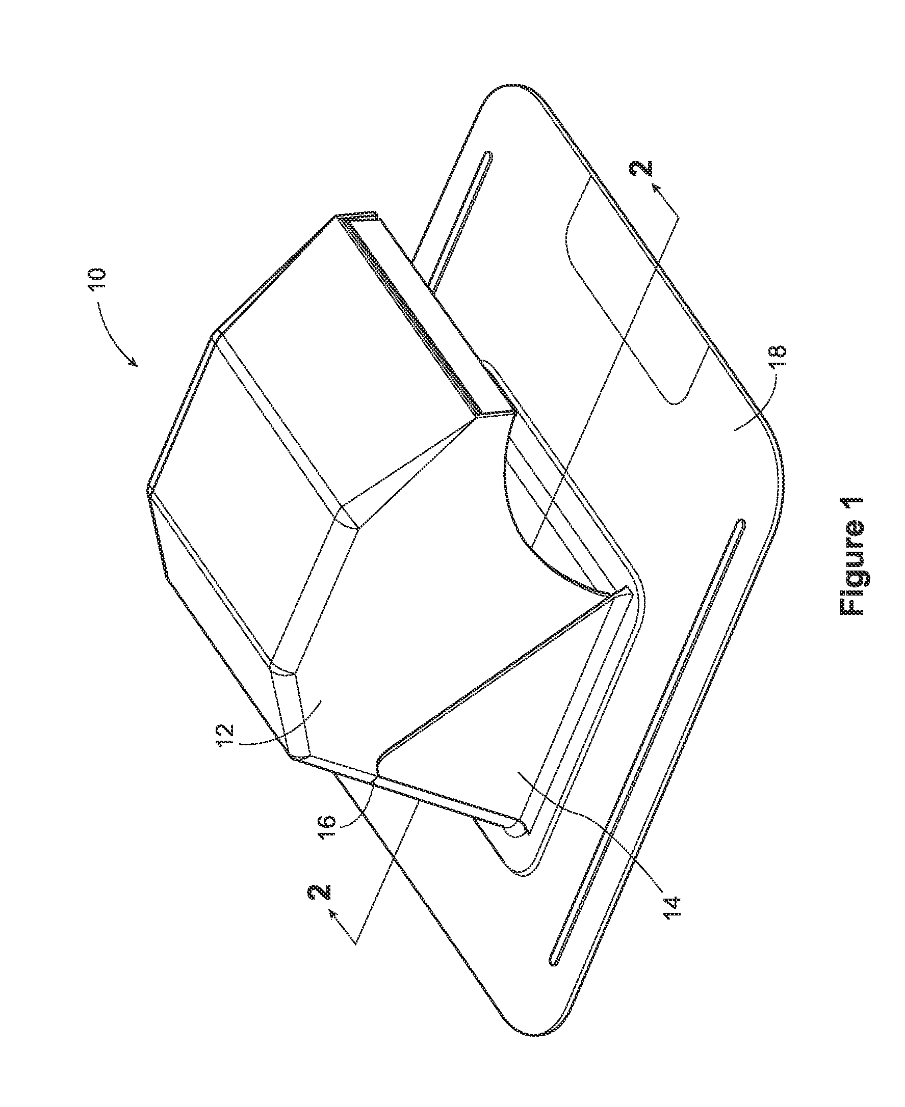
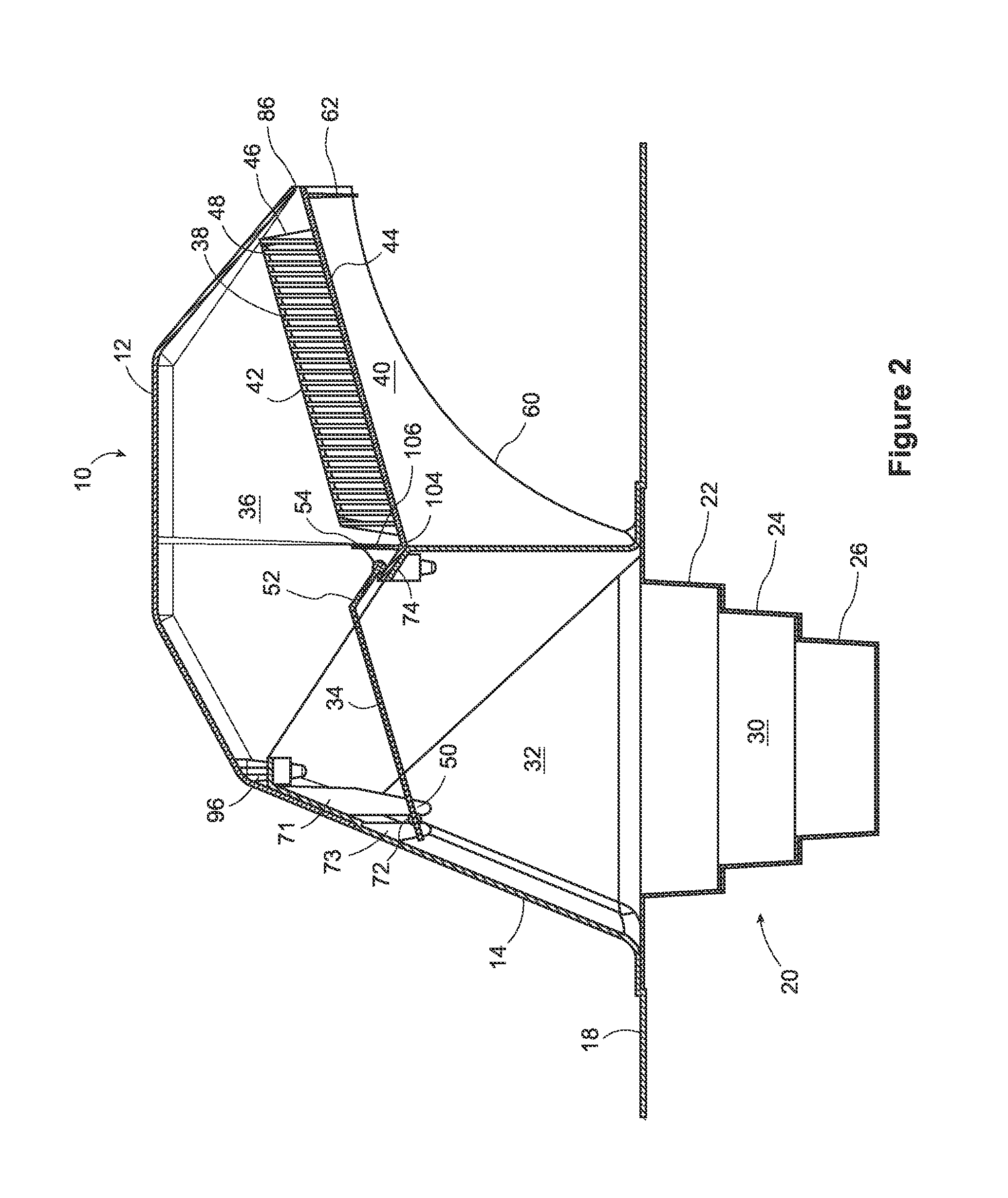
[0024]A gooseneck style vent, according to a preferred embodiment of the invention, is shown as 10 in FIG. 1. It includes a top 12 and a base 14. A join line 16 exists between the base 14 and the top 12. The base also includes a nailing flange 18 and a duct connector 20 (FIG. 2) extending from said base 14 on an opposite side to said top

[0025]FIG. 2 is a cross-sectional view through the duct connector 20, the base 14 and the top 12. As can be seen, the duct connector 20 includes at least two and in a preferred embodiment three different sized connectors for connecting to different sized ducts. These are shown as 22, 24 and 26 respectively. Most preferably, an installer would determine the duct size being connected to the duct and would remove with a knife or other sharp edge any connector sections which were too small. In this way a single connector can be made adaptable to at least two and preferably three standard duct sizes.

[0026]The vent 10 of the present invention defines an ai...


PUM


Abstract

A goose neck style vent has a base that registers with a surface opening of a building, and upstanding walls which form a portion of a curved air flow pathway above the vent opening. A top portion of the vent registers with the base to complete the curved air flow pathway and define an air outlet opening. The top includes a screen that hinges to cover the air outlet opening. A flapper valve is positioned across the curved air flow pathway and is hinged to the base at one end. The opposite free end of the flapper valve is urged to a closed position by gravity and to an open position by air pressure from below. An upstanding air deflecting baffle extends above the free end of the flapper, and limits air gusts passing through the screen and under the free end of the flapper valve.

Description

FIELD OF THE INVENTION[0001]This invention relates generally to the field of ventilation products and more particularly to exterior vents of the type that are used to vent the inside of buildings. Most particularly this invention relates to exterior vents which may be used to vent air from bathrooms, kitchens, dryers and the like or to allow air into the building in certain circumstances.BACKGROUND OF THE INVENTION[0002]Modern buildings are being made ever more energy efficient which often translates into better insulation and less air infiltration through cracks, gaps or the like. As a consequence, the airflow into and out of the building envelope must be very carefully managed.[0003]Another consequence of a tighter building envelope however is the need to manage the exhaust air flow which may be required from other building systems. Three systems in particular have localized blowers to force vent air in certain circumstances, and they include bathroom exhaust fans, to vent moistur...

Claims


Application Information

Patent Timeline
Patent Type & Authority Applications(United States)
IPC IPC(8): F24F13/10F24F13/20F24F7/02
CPCF24F13/10F24F13/20F24F7/02F24F13/082F24F13/14
Inventor MANTYLA, JAMESBALDWIN, SCOTT
Owner CANPLAS INDS
Why Eureka
Try Eureka