Method and systems for exhaust gas recirculation valve diagnosis based on crankcase pressure

Active Publication Date: 2016-05-19
GE GLOBAL SOURCING LLC
View PDF5 Cites 22 Cited by
  • Summary
  • Abstract
  • Description
  • Claims
  • Application Information

AI Technical Summary

Problems solved by technology

Under some conditions, the one or more valves may become stuck in undesired positions, or may be inadvertently mis-positioned.
Furthe

Method used


Image

  • Method and systems for exhaust gas recirculation valve diagnosis based on crankcase pressure
  • Method and systems for exhaust gas recirculation valve diagnosis based on crankcase pressure
  • Method and systems for exhaust gas recirculation valve diagnosis based on crankcase pressure

Examples


Embodiment Construction

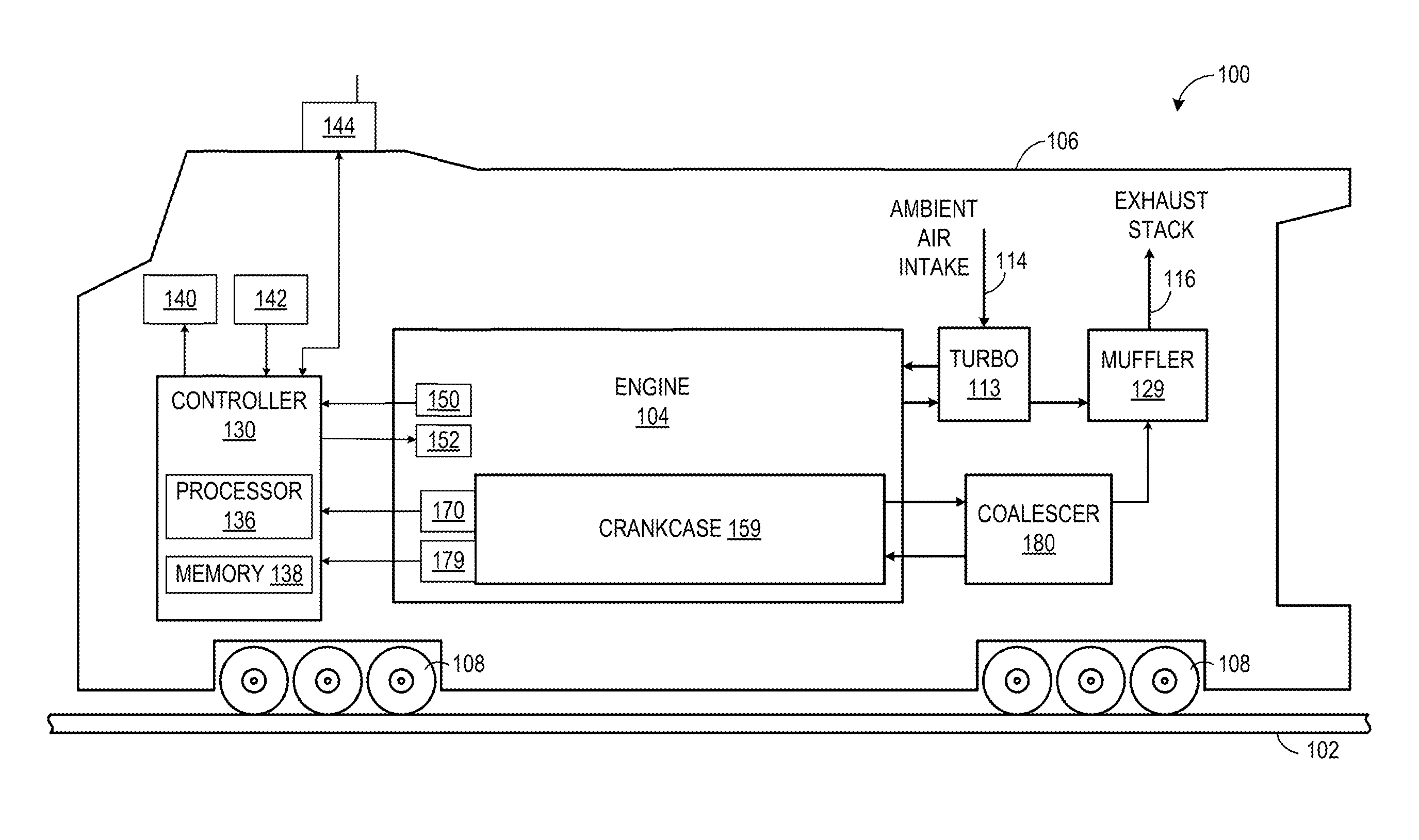
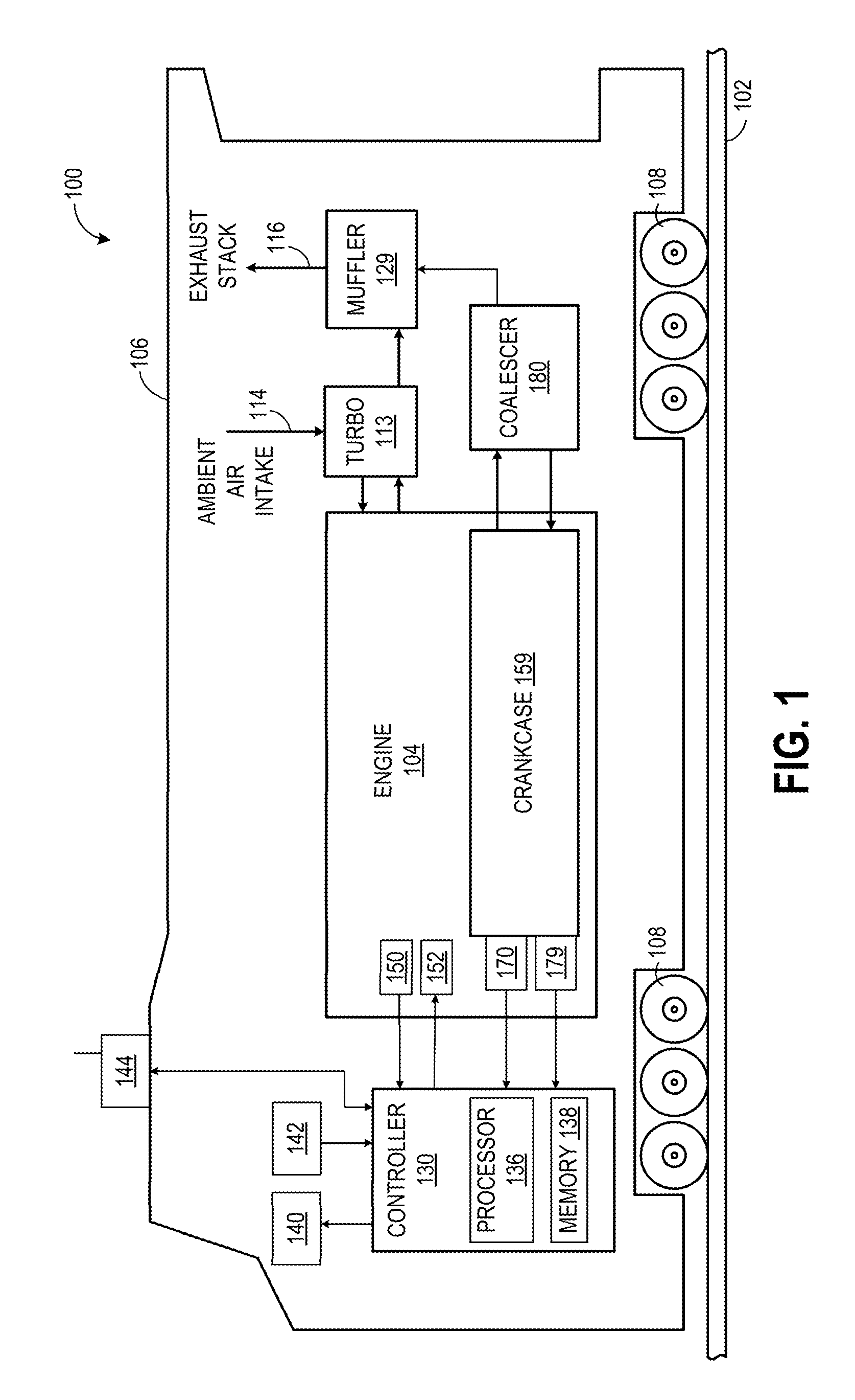
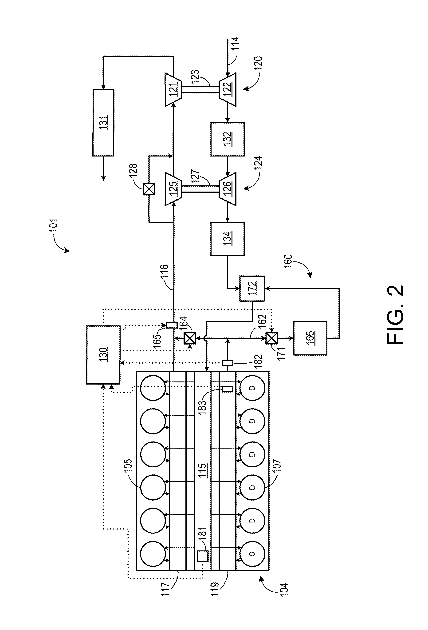
[0014]The following description relates to embodiments of methods and systems for indicating a condition of a valve disposed in a first exhaust passage downstream from a cylinder exhaust valve based at least in part on a crankcase pressure. In one example, the valve is one of a first valve and a second valve of an exhaust gas recirculation (EGR) system of an engine. The EGR system may selectively route exhaust from the engine to a second exhaust passage via the first valve and to an intake passage via the second valve. In one example, indicating the condition of the first valve and / or the second valve may include indicating one or more of mis-positioning, degradation, sticking, or leaking of one or more of the first valve and the second valve. As a result, engine servicing and / or valve checking routines may be targeted based on the condition of the two valves.

[0015]FIG. 1 shows an embodiment of a vehicle including an engine having a crankcase. FIG. 2 shows an embodiment of an engine...


PUM


Abstract

Various methods and systems are provided for diagnosing an exhaust gas recirculation valve based on crankcase pressure. In one example, a method comprises indicating a condition of a valve disposed in a first exhaust passage downstream from a cylinder exhaust valve based at least in part on a crankcase pressure.

Description

BACKGROUND[0001]1. Technical Field[0002]Embodiments of the subject matter disclosed herein relate to engines. Other embodiments relate to engine diagnostics.[0003]2. Discussion of Art[0004]Engines may utilize recirculation of exhaust gas from an engine exhaust system to an engine intake system, a process referred to as exhaust gas recirculation (EGR), to reduce regulated emissions. Some EGR systems may include one or more valves to direct exhaust to an intake passage and / or an exhaust passage of the engine based on a desired amount of EGR. Under some conditions, the one or more valves may become stuck in undesired positions, or may be inadvertently mis-positioned. Further still, degradation of one or more of these valves may result in degradation in engine performance and / or eventual engine shutdown.BRIEF DESCRIPTION[0005]In one embodiment, a method for an engine (e.g., a method for controlling an engine system) comprises indicating a condition of a valve disposed in an exhaust pass...

Claims


Application Information

Patent Timeline
IPC IPC(8): F02M25/07G01L11/04
CPCF02M25/0702F02M25/0706G01L11/04F02M25/0724F02M25/077F02M25/0717G01M15/08F02M26/49F02M26/52F02D41/0077F02D41/221F02M25/06F01M2013/0083F02M26/08F02M26/10F02M26/23F02M26/43Y02T10/40F02D41/22
Inventor PETERS, ERIC DAVIDHANSEN, NICHOLAS ERIC
Owner GE GLOBAL SOURCING LLC
Why Eureka
Try Eureka