
Fmcw radar device and fmcw radar signal processing method

a radar and signal processing technology, applied in the field of frequency modulated continuous wave (fmcw) radar devices and fmcw radar signal processing methods, can solve the problem of expensive devices and achieve the effect of low cos

Active Publication Date: 2016-05-19
MITSUBISHI ELECTRIC CORP
View PDF2 Cites 16 Cited by
  • Summary
  • Abstract
  • Description
  • Claims
  • Application Information

AI Technical Summary

Benefits of technology

The present invention introduces an FMCW radar device and signal processing method that can detect multiple targets and measure their distance and speed with low-deflection radar. The goal is to provide a cost-effective solution for detecting targets and measuring their distance and speed.

Problems solved by technology

However, the related art has the following problem.
Accordingly, the related-art FMCW radar device needs to include the plurality of BPFs and switches, resulting in a problem in that the device is expensive.

Method used


Image

  • Fmcw radar device and fmcw radar signal processing method
  • Fmcw radar device and fmcw radar signal processing method
  • Fmcw radar device and fmcw radar signal processing method

Examples


first embodiment

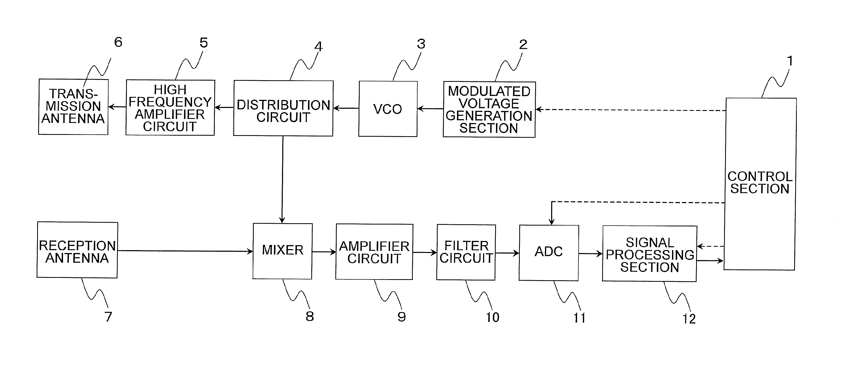
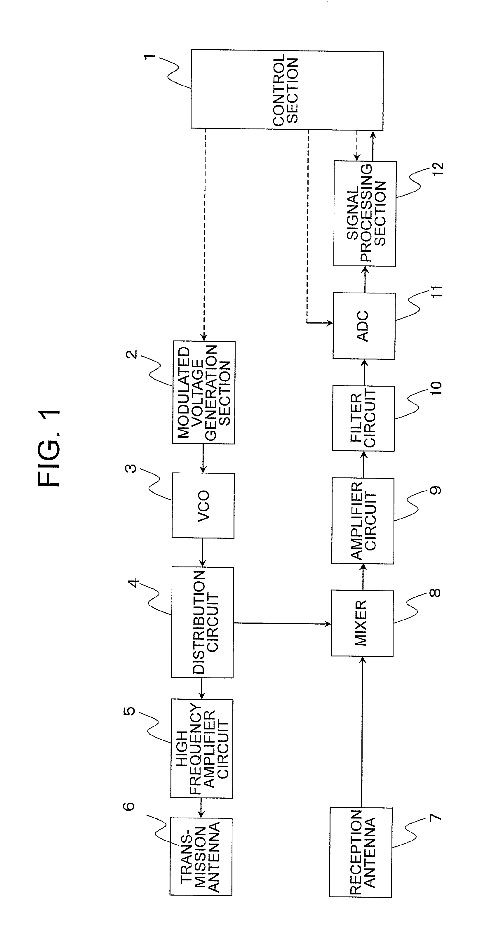
[0020]FIG. 1 is a block diagram illustrating an FMCW radar device according to a first embodiment of the present invention.

[0021]In FIG. 1, the FMCW radar device includes a control section 1, a modulated voltage generation section (range observation period setting section, modulated frequency width setting section) 2, a voltage-controlled oscillator (hereinafter referred to as “VCO”) 3, a distribution circuit 4, a high frequency amplifier circuit 5, a transmission antenna 6, a reception antenna 7, a mixer (beat signal generation section) 8, an amplifier circuit 9, a filter circuit (pass bandwidth setting section) 10, an ADC 11, and a signal processing section 12.

[0022]In this case, the control section 1, the modulated voltage generation section 2, and the signal processing section 12 are each formed of, for example, a dedicated logic circuit, a program in a general-purpose CPU or digital signal processor (DSP), or a combination thereof, and a data storage memory.

[0023]The control se...


PUM


Abstract

The FMCW radar device includes: a range observation period setting section configured to set a plurality of range observation periods; a modulated frequency width setting section configured to set, for the respective plurality of range observation periods, a plurality of modulated frequency widths; a beat signal generation section configured to generate, for the respective plurality of range observation periods, beat signals based on the transmission signal and the reception signal; and a pass bandwidth setting section configured to set pass bandwidths of the beat signals generated by the beat signal generation section, in which the modulated frequency width setting section sets, for the respective plurality of range observation periods, the plurality of modulated frequency widths so that a difference among maximum frequencies of the beat signals generated for the respective plurality of range observation periods becomes zero or falls within a predetermined range.

Description

BACKGROUND OF THE INVENTION[0001]1. Field of the Invention[0002]The present invention relates to a frequency modulated continuous wave (FMCW) radar device and an FMCW radar signal processing method for detecting an object serving as a target (hereinafter simply referred to as “target”), and measuring a distance to the target and a speed relative to the target.[0003]2. Description of the Related Art[0004]In recent years, an FMCW radar device (hereinafter also simply referred to as “FMCW radar”) is used, which can deal with a target at a distance of several hundred meters with a less expensive and simpler configuration than a pulse radar and other radars. The FMCW radar radiates (transmits) a transmission signal subjected to specific modulation as an electromagnetic wave, receives the electromagnetic wave reflected by a target as a reception signal, and generates a beat signal based on the transmission signal and the reception signal.[0005]Further, the beat signal is converted into di...

Claims


Application Information

Patent Timeline
Patent Type & Authority Applications(United States)
IPC IPC(8): G01S13/58G01S7/35G01S13/931
CPCG01S13/584G01S2007/356G01S7/35G01S7/03G01S7/354G01S13/345G01S13/726G01S13/931G01S7/356
Inventor YAMASHINA, NORIYOSHI
Owner MITSUBISHI ELECTRIC CORP
Learn More