Hydraulic control system for use with a turf sweeper

a control system and hydraulic technology, applied in the field of hydraulic control systems for turf sweepers, can solve the problems of foreign matter that cannot be separated from the turf, previous hydraulically powered turf sweepers lacked appropriate safety and control systems, previous turf sweepers lacked component safety controls that prevent sudden changes in the rotational direction or speed of the rotatable brush

Inactive Publication Date: 2016-05-26
BROCE MFG CO
View PDF0 Cites 0 Cited by
  • Summary
  • Abstract
  • Description
  • Claims
  • Application Information

AI Technical Summary

Benefits of technology

[0008]In a yet further aspect, the process includes preventing the rotatable brush from changing the direction of its rotation in response to a change in the setting of the directional adjuster if the brush speed adjuster is not set to the zero setting.
[0015]In an even further aspect of the system, the system includes a controller wherein the controller is in communication with the directional adjuster, the brush speed adjuster, the proportional control valve and the directional control valve, monitors the setting of the directional adjuster and the brush speed adjuster and causes the proportional control valve to adjust in response to adjustment of the brush speed adjuster. The controller further causes the directional control valve to adjust in response to adjustment of the directional adjuster. The controller further prevents the directional control valve from directing hydraulic fluid to the hydraulic motor if the brush speed adjuster is not set to the zero setting when the turf sweeper is turned on and causes the directional control valve to direct hydraulic fluid to the hydraulic motor if the brush speed adjuster is set to the zero position at or after the time when the turf sweeper is turned on and the brush speed adjuster is subsequently adjusted to the maximum position or at least one intermediate position.
[0017]In a still even further aspect of the system, the controller will not cause the directional control valve to adjust such that the rotatable brush changes rotational direction if the brush speed adjuster is not in the zero setting.

Problems solved by technology

The brush bristles of the rotatable brush contact the turf and cause foreign matter to separate from the turf.
Previous hydraulically powered turf sweepers lacked appropriate safety and control systems.
More specifically, previous turf sweepers lacked component safety controls that prevent sudden changes in the rotational direction or speed of the rotatable brush.
Accordingly, previous turf sweepers were subject to damage or safety concerns due to sudden changes in rotational direction and speed.

Method used


Image

  • Hydraulic control system for use with a turf sweeper
  • Hydraulic control system for use with a turf sweeper
  • Hydraulic control system for use with a turf sweeper

Examples


Embodiment Construction

[0030]In the description that follows, like parts are marked throughout the specification and drawings with the same reference numerals, respectively. The drawings are not necessarily to scale and the proportions of certain parts have been exaggerated to better illustrate details and features of the invention. Where components of relatively well-known designs are employed, their structure and operation will not be described in detail.

[0031]The current disclosure is directed to a hydraulic control system utilizing a hydraulic integrated circuit (HIC) for variable control of the speed and direction of a hydraulic motor. For example, the system of this disclosure can be useful to control the brush of a turf sweeper.

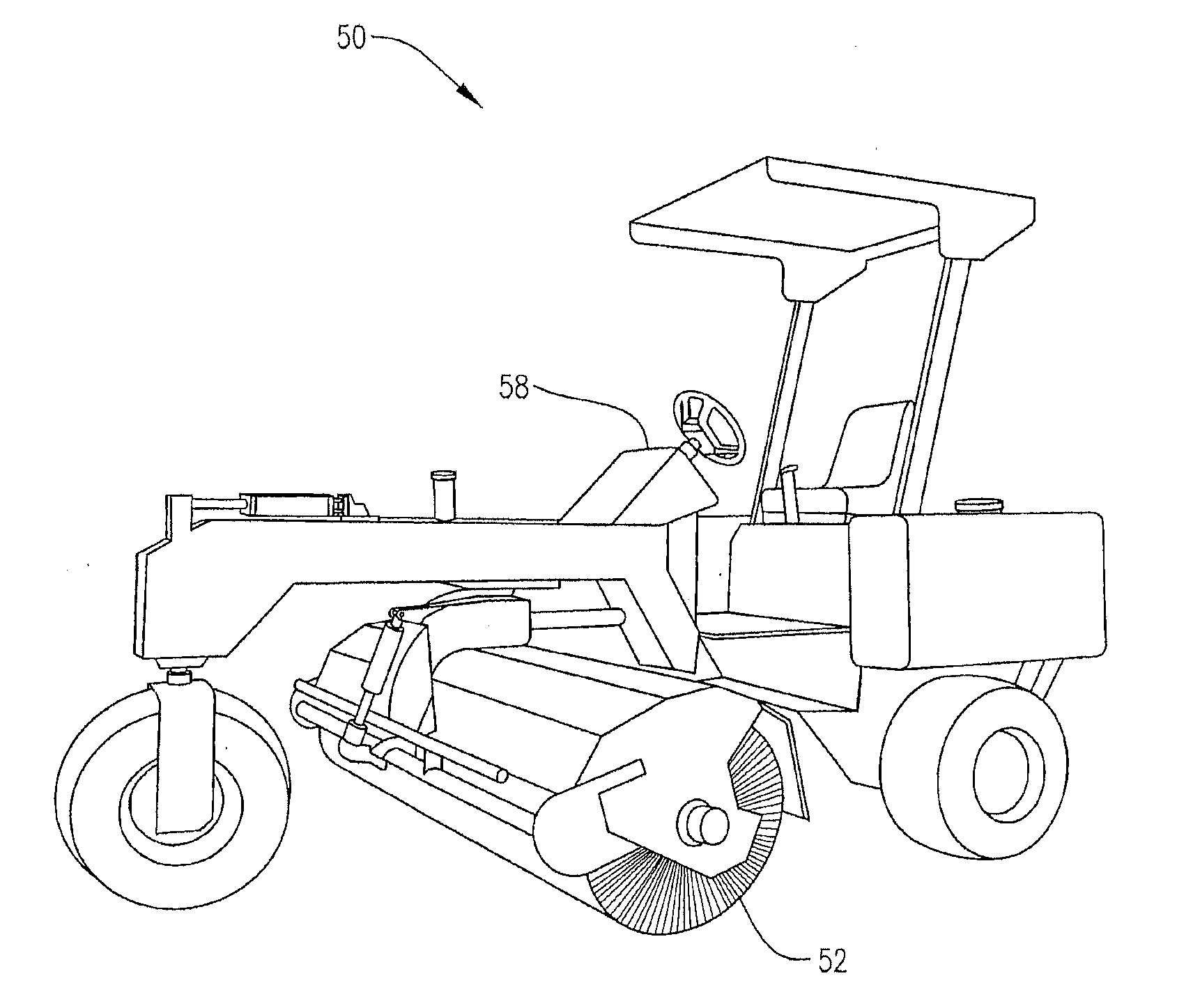
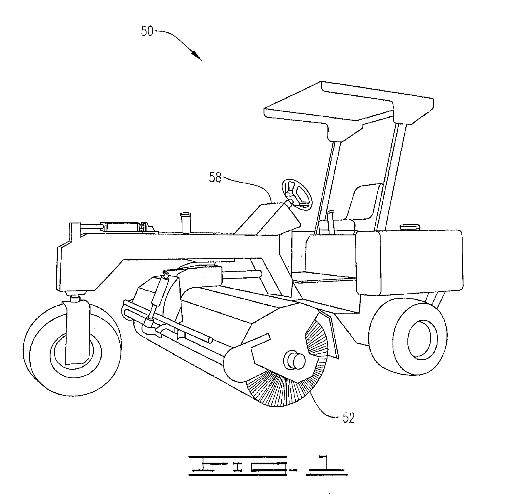
[0032]FIG. 1 shows a turf sweeper 50 in which the present hydraulic system can be used. Turf sweeper 50 comprises a rotatable brush 52. Typically, a hydraulic motor 3 (FIG. 3) causes the rotatable brush to rotate at a desired speed. The hydraulic motor is controlled by HIC 1...


PUM


Abstract

A turf sweeper with a rotatable brush including an adaptable hydraulic control system is disclosed. The turf sweeper includes a controller adapted to modify the hydraulic system to affect the rotational speed and direction of the rotatable brush. The controller and hydraulic control system are adapted such that the rotatable brush will not rotate if the turf sweeper is turned on and the speed adjuster for the rotatable brush is not set to the zero speed setting.

Description

CROSS-REFERENCE TO RELATED APPLICATION[0001]This application claims the benefit of U.S. Provisional Application No. 61 / 842,155 filed Jul. 2, 2013, which is hereby incorporated by reference.FIELD OF THE INVENTION[0002]The present process and system relate to turf sweepers and, more specifically, to turf sweepers using hydraulic control systems.BACKGROUND OF THE INVENTION[0003]Turf sweepers are typically used to collect debris on turf. Turf sweepers may be towed or self propelled and operate by contacting turf with a rotatable brush. The brush bristles of the rotatable brush contact the turf and cause foreign matter to separate from the turf. The rotatable brush in the turf sweeper can be powered by a hydraulic system.[0004]Previous hydraulically powered turf sweepers lacked appropriate safety and control systems. More specifically, previous turf sweepers lacked component safety controls that prevent sudden changes in the rotational direction or speed of the rotatable brush. According...

Claims


Application Information

Patent Timeline
Patent Type & Authority Applications(United States)
IPC IPC(8): A01G1/12
CPCA01G1/125A01G20/43
Inventor MCCART, MARK A.
Owner BROCE MFG CO
Why Eureka
Try Eureka