A linear air pressure balanced ultrasonic atomization device

A technology of air pressure balance and ultrasonic atomization, which is applied in the direction of spraying devices and liquid spraying devices, can solve the problems of unfavorable factory space, inconvenient connection of front and rear devices, and increased load of drive motors, so as to facilitate equipment installation and avoid direction changes , Improve the effect of stability

Active Publication Date: 2019-06-14
李东林 +2
View PDF2 Cites 0 Cited by
  • Summary
  • Abstract
  • Description
  • Claims
  • Application Information

AI Technical Summary

Problems solved by technology

[0007] 1. The workpiece conveying channel of the processing device is U-shaped in the plane projection direction, and it is inconvenient to connect with the front and rear devices on the entire coating process line, which is not conducive to the rational use of workshop space
[0008] 2. Since the workpiece conveying channel is a U-shaped turning structure, the chain rails in the workpiece conveying channel must be arranged according to the shape, resulting in high cost of structural parts, and difficulties in alignment and installation, which in turn lead to high equipment costs
[0009] 3. The workpiece conveying channel adopts a U-shaped structure. The guide rail for the workpiece conveying chain in the workpiece conveying channel has two position changes along the horizontal direction. Both position changes will cause radial friction, which will increase the load on the drive motor. , so that the chain rail is also very easy to wear, and at the same time, the workpieces are likely to collide with each other at two corner positions during the operation of the workpiece, causing unnecessary troubles

Method used


Image

  • A linear air pressure balanced ultrasonic atomization device
  • A linear air pressure balanced ultrasonic atomization device
  • A linear air pressure balanced ultrasonic atomization device

Examples


Embodiment Construction

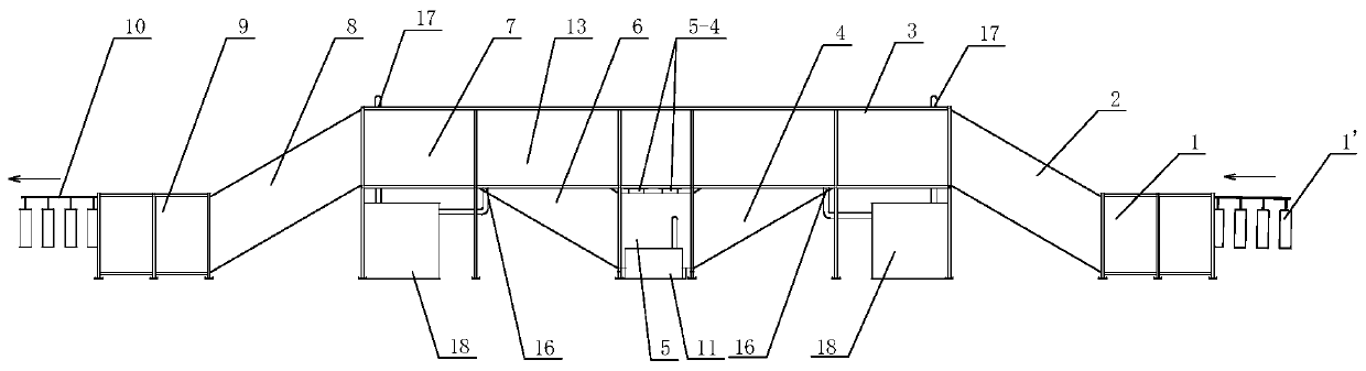
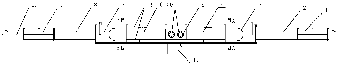
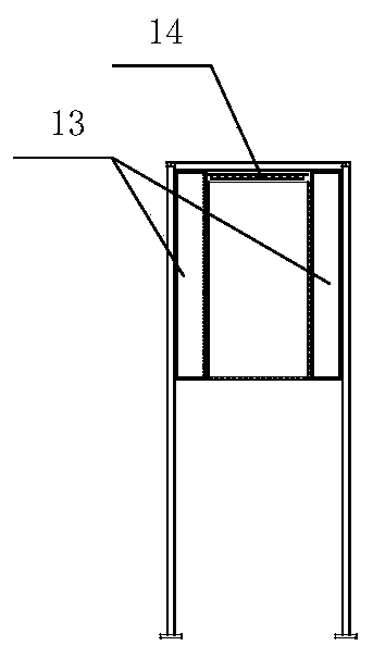
[0032] In order to further understand the invention content, characteristics and effects of the present invention, the following examples are given, and detailed descriptions are as follows in conjunction with the accompanying drawings:

[0033] see Figure 1-7 , a linear air pressure balanced ultrasonic atomization device, including a workpiece conveying channel, the workpiece conveying channel is composed of a channel section 1 in the low-level entry area, a channel section 2 in the climbing area before fog coating, a channel section 3 in the high-level area before fog coating, and a fog coating. Channel section 4 in the downhill area before coating, channel section 5 in the low fog coating area, channel section 6 in the climbing area after fog coating, channel section 7 in the high level area after fog coating, channel section 8 in the downhill area after fog coating, and the low delivery area The channel segments 9 are successively connected and formed. Specifically, the ...


PUM


Abstract

The invention discloses a linear air pressure balance type ultrasonic atomization device. The linear air pressure balance type ultrasonic atomization device comprises a workpiece conveying channel which is overall linear in the plane projection direction. The workpiece conveying channel is formed by sequentially connecting a low-position workpiece inlet area channel section, an atomization coating front uphill area channel section, an atomization coating front high-position area channel section, an atomization coating front downhill area channel section, a low-position atomization coating area channel section, an atomization coating rear uphill area channel section, an atomization coating rear high-position area channel section, an atomization coating rear downhill area channel section and a low-position workpiece discharging area channel section. High-position air flow circulation channels are connected to the outer portion of the atomization coating front high-position area channel section and the outer portion of the atomization coating rear high-position area channel section. An inlet air curtain machine is arranged at an inlet of the upper end of the atomization coating front downhill area channel section, and an outlet air curtain machine is arranged at an outlet of the upper end of the atomization coating rear uphill area channel section. A waste gas treatment device is connected between a waste gas exhaust connecting opening of the atomization coating front downhill area channel section and a clean air input connecting opening of the atomization coating front high-position area channel section, and a waste gas treatment device is connected between a waste gas exhaust connecting opening of the atomization coating rear uphill area channel section and a clean air input connecting opening of the atomization coating rear high-position area channel section. By means of the device, front and rear equipment connecting on a coating technological line is facilitated.

Description

technical field [0001] The invention belongs to the technical field of metal surface treatment, in particular to a linear air pressure balanced ultrasonic atomization device. Background technique [0002] Coating is an important link in the surface manufacturing process of construction machinery products. Metal pretreatment is an indispensable and important process in painting, and it is a key link to improve the adhesion, corrosion resistance and decoration of the coating film. The level of metal pretreatment is directly related to the quality of the coating, which in turn is related to the life of the coated product, the size of the market competitiveness, and even the value of the coated product. The traditional metal surface pretreatment process is cumbersome and complex, with high energy consumption, demanding process conditions, poor quality stability, and a large number of staffing. The implementation process is accompanied by a large amount of waste water, waste aci...

Claims


Application Information

Patent Timeline
Patent Type & Authority Patents(China)
IPC IPC(8): B05B17/06B05B13/02
CPCB05B13/0221B05B17/06
Inventor 李东林宫汝祥唐庆东
Owner 李东林
Why Eureka
Try Eureka