
Arrangement for indicating the state of the lock of a door with indication lights, and a face plate

a technology for indicating the state of the lock and the door, which is applied in the direction of the handle, the door/window fitting, the wing knob, etc., can solve the problems of extra work and costs, and the type of installation might also detract from the elegance/appearance of the door

Inactive Publication Date: 2016-05-26
ROLLOCK
View PDF3 Cites 16 Cited by
  • Summary
  • Abstract
  • Description
  • Claims
  • Application Information

AI Technical Summary

Benefits of technology

The invention has two main advantages. Firstly, the lock case has its own separate light indication system, which means that there is no need to have extra holes or machining procedures in the door. This saves money and makes the door look better. Secondly, the light indication system is compact and can be easily installed, so there are no additional work phases required. The invention can be used with any handle on the market.

Problems solved by technology

This causes extra work and costs.
These types of installations might also detract from the elegance / appearance of the door.

Method used


Image

  • Arrangement for indicating the state of the lock of a door with indication lights, and a face plate
  • Arrangement for indicating the state of the lock of a door with indication lights, and a face plate
  • Arrangement for indicating the state of the lock of a door with indication lights, and a face plate

Examples


Embodiment Construction

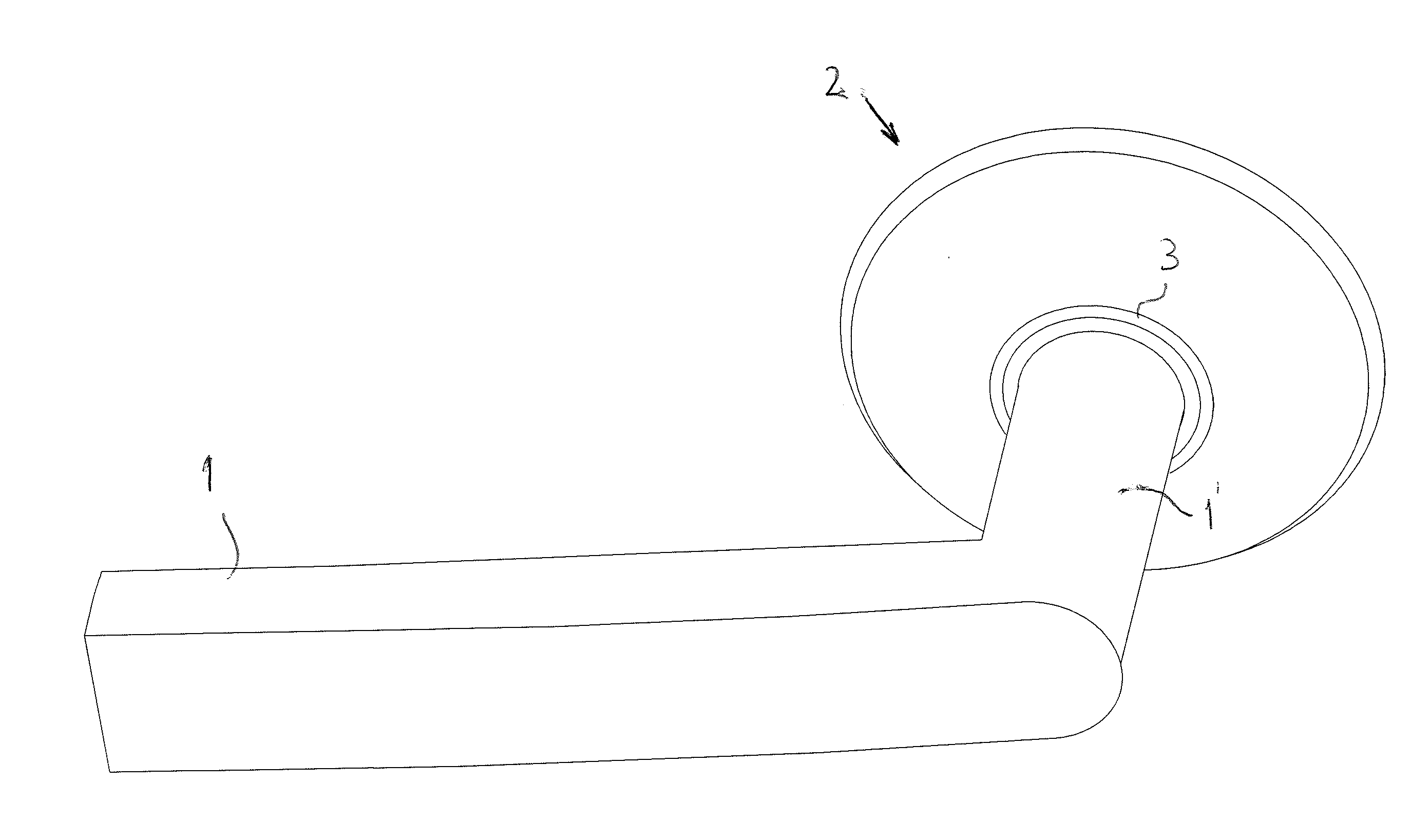
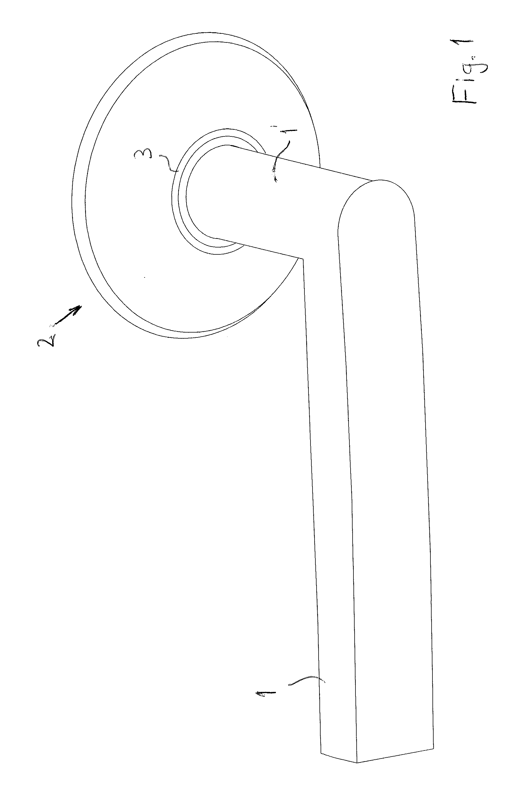
[0017]FIG. 1 thus presents a combination of a handle 1 and a face plate 2 according to the invention. The handle 1 thus refers to a doorhandle. The stem part 1′ of the handle 1 goes through the hole in the center of the face plate 2. The task of the face plate is to cover the lock housing, as is known in the art. The lock, of course, comprises a lock case installed in the lock housing, which lock case is not presented in the drawings.

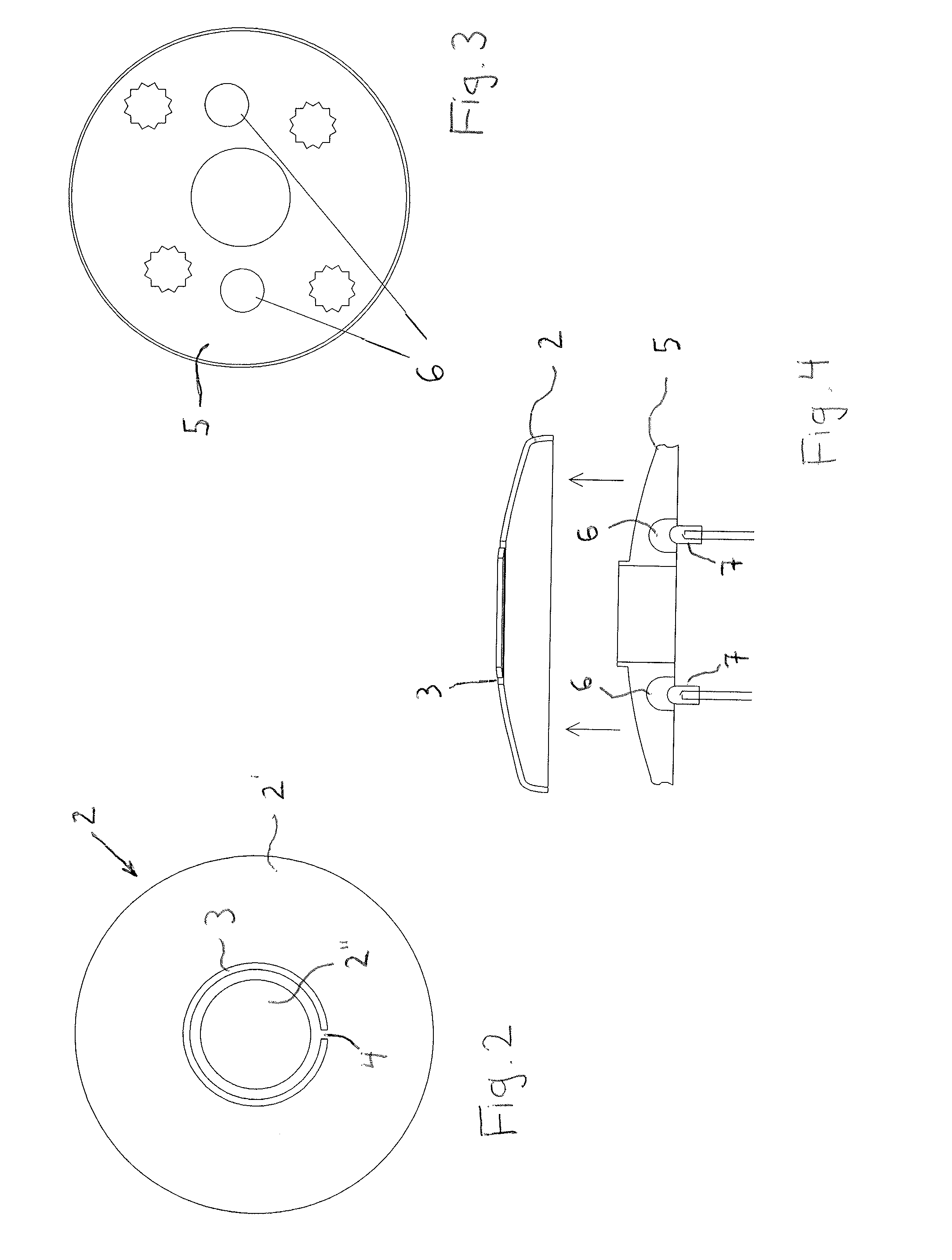
[0018]An essentially ring-shaped aperture or groove, which is presented with the reference number 3, is made in the face plate according to the invention. The shape of the aperture 3 is shown in more detail in FIG. 2. It is thus an essentially ring-shaped groove, in which a small fixing bridge 4 is left between the rest of the face plate 2′ and the center part 2″ of the face plate. The fixing bridge 4 must therefore exist for the center part 2″ of the face plate to stay attached to the rest of the face plate 2″. The ring-shaped aperture 3 forming an alm...


PUM


Abstract

Arrangement for indicating the state of the lock of a door with indication lights, which lock includes a lock case installed in a lock housing inside the door, a handle for opening the door, and a face plate installed onto the surface of the door. The face plate covers the lock housing and through which the handle is installed. Indication lights are installed in the lock case behind the face plate, and at least one aperture is made in the face plate, through which the light is visible from the front of the door.

Description

FIELD OF TECHNOLOGY[0001]The object of the present invention is an arrangement for indicating the state of the lock of a door with indication lights, which lock comprises a lock case installed in a lock housing inside the door, a handle, by means of which the door is opened, and a face plate installed onto the surface of the door, which face plate covers the lock housing and through which the handle is installed.PRIOR ART[0002]The invention thus relates to the locks of doors, said locks comprising at least a lock case, a face plate on the surface of the door, and a handle (doorhandle) installed in the normal way through the face plate, by means of which door handle the door is finally opened:[0003]The invention further relates to those types of door locks in. which indication lights are used to indicate the state of the lock. The lights can be many different colors. For example, green can mean that the lock can be opened by pressing the handle, red can indicate that the lock cannot ...

Claims


Application Information

Patent Timeline
Patent Type & Authority Applications(United States)
IPC IPC(8): E05B17/10E05B1/00E05B9/02E05B41/00
CPCE05B17/10E05B41/00E05B9/02E05B1/0061E05B1/0053E05B15/02E05B1/0084
Inventor KANKKUNEN, HANNU
Owner ROLLOCK
Learn More