Pose determination from a pattern of four leds

Active Publication Date: 2016-05-26
ASELSAN ELEKTRONIK SANAYI & TICARET ANONIM SIRKETI
View PDF5 Cites 6 Cited by
  • Summary
  • Abstract
  • Description
  • Claims
  • Application Information

AI Technical Summary

Problems solved by technology

However we have two problems which require solution to its dual to be correctly solvable.
Such effort is necessary since it is possible that tracked object may leave view frustum of the camera then comes back to it.
Solving initial correspondence problem with current methods requires many f

Method used


Image

  • Pose determination from a pattern of four leds
  • Pose determination from a pattern of four leds
  • Pose determination from a pattern of four leds

Examples


Embodiment Construction

[0010]A system and method realized to fulfill the objective of the present invention is illustrated in the accompanying FIGS., in which:

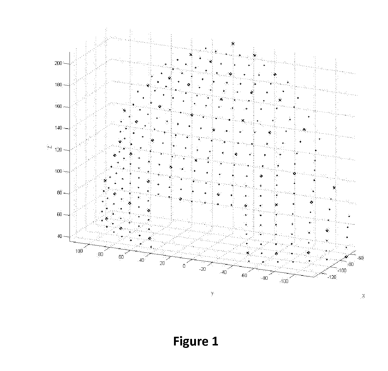
[0011]FIG. 1 shows graph of a mesh of possible fiducial positions on the object.

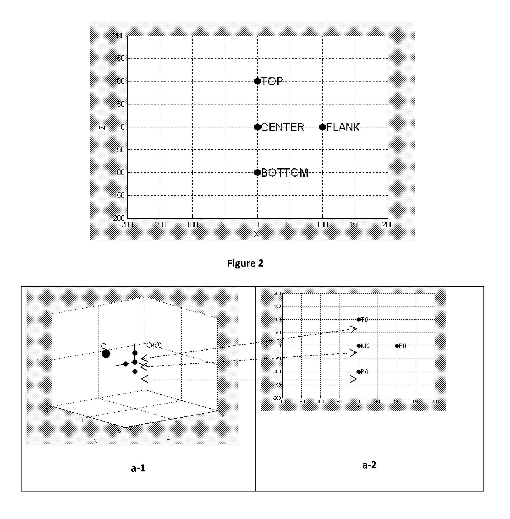
[0012]FIG. 2 shows sample placement of LED group of four.

[0013]FIG. 3 shows an example of pose ambiguity problem.

[0014]FIG. 3-a shows an example of LED group projection with object elevation 0 degrees.

[0015]FIG. 3-b shows an example of LED group projection with object elevation −45 degrees.

[0016]FIG. 3-c shows an example of LED group projection with object elevation +45 degrees.

[0017]FIG. 4 is the flowchart of the method for solving correspondence problem.

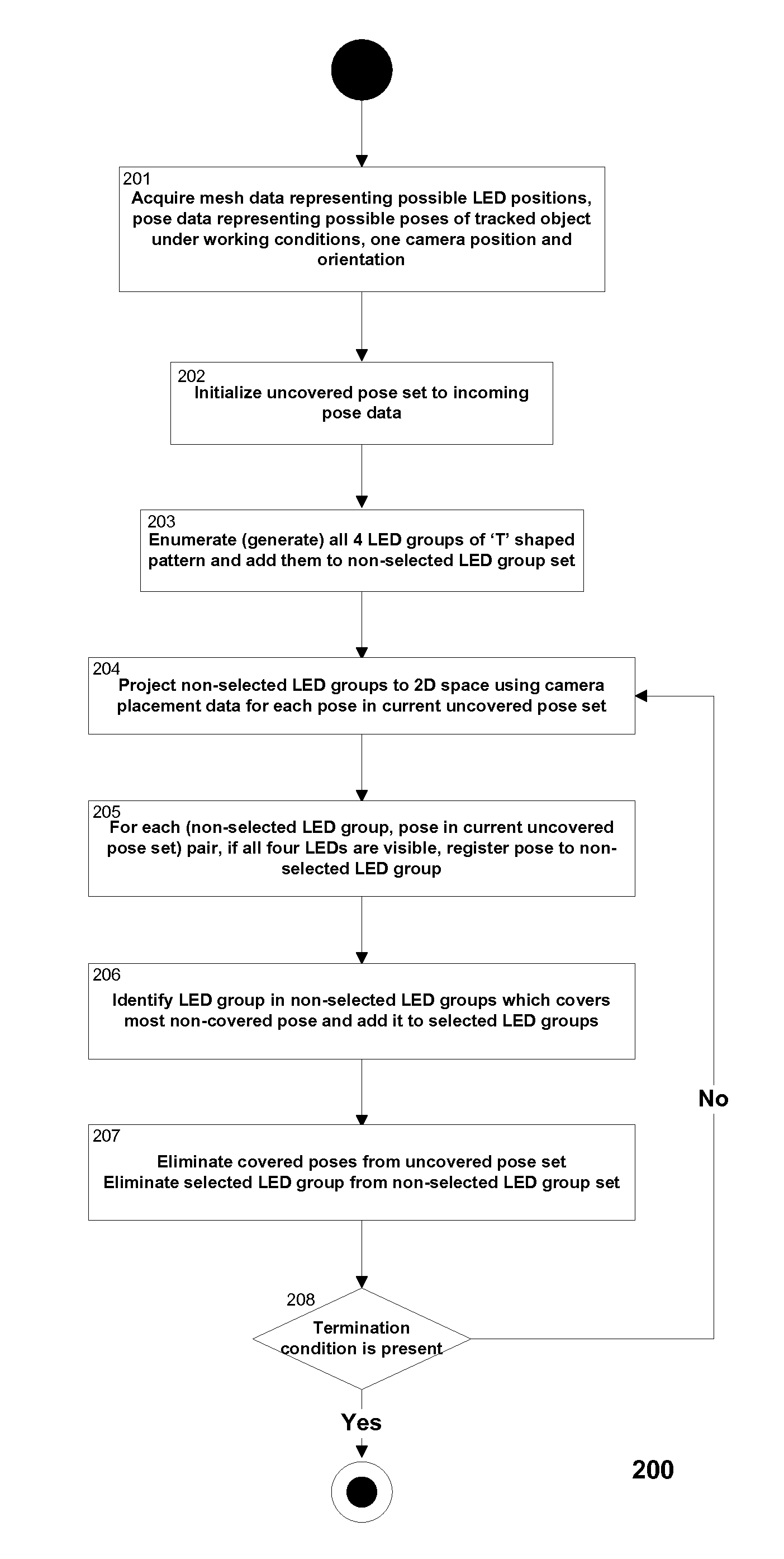
[0018]FIG. 5 is the flowchart of the method for selecting LED groups to be used for solving correspondence problem.

[0019]100. Method for solving correspondence problem.

[0020]200. Method for selecting LED groups to be used for solving correspondence problem.

[0021]C. Camera

[0022]O0. Object elevation (0)

[0023]O1. Object el...


PUM


Abstract

The present invention relates to the field of computation and covers methods to find one to one mapping between fiducial markers on a tracked object and fiducial marker projections on the image plane captured by a camera in optical object tracking systems. A method for solving correspondence problem is realized to find correspondences between 3D points of an object and 2D projection of that object onto the image plane so that this can be used to find the object's 3D location and orientation. It is designed to work without current pose of the tracked object thus it is equally efficient on initial correspondence problem as correspondence problem. Furthermore, a method for selecting LED groups to be used for solving correspondence problem is also presented, which uses pose data representing possible poses of tracked object under working conditions thus LEDS groups are selected to satisfy use case requirements.

Description

FIELD OF THE INVENTION[0001]The present invention relates to the field of computation and covers methods to find one to one mapping between fiducial markers on a tracked object and fiducial marker projections on the image plane captured by a camera in optical object tracking systems.BACKGROUND OF THE INVENTION[0002]It is known that there are methods and models to track a three dimensional object in an environment and compute its position and orientation (pose) with respect to a predetermined coordinate system. These kinds of tracker systems are used for example in aircrafts to determine the orientation of head of the pilot. Once the orientation is acquired with respect to the coordinate system of say the display devices, then it is possible to generate graphics on these accordingly. There are different methods to track an object in the scene using magnetic, mechanical or optical means. Currently, the spatial relations of objects may also be determined using magnetic sensors or laser...

Claims


Application Information

Patent Timeline
IPC IPC(8): G06K9/00H04N5/235G06T7/20G06K9/20H04N5/225
CPCG06K9/00375G06K9/2027H04N5/2256G06T2207/30204H04N5/2354G06K9/2054G06T7/2033G06T2207/10048G06T2207/30208G06T7/73G06T7/246G06V40/107H04N23/56H04N23/74
Inventor BICER, KADIR HAKANOKUYAN, ERKAN
Owner ASELSAN ELEKTRONIK SANAYI & TICARET ANONIM SIRKETI
Why Eureka
Try Eureka