High elongation steel cord and pneumatic tire comprising said cord

Inactive Publication Date: 2016-06-02
NV BEKAERT SA
View PDF10 Cites 10 Cited by
  • Summary
  • Abstract
  • Description
  • Claims
  • Application Information

AI Technical Summary

Benefits of technology

[0005]The primary object of the invention is to provide a high elongatio

Problems solved by technology

When the steel cord is further stretched, the steel cord may break and result in the elongation at break.
But this structure faces the problem for rubber penetration, wherein the steel cord cannot be embedded in the rubber matrix properly, and eventually corrosion occurs and limits the life time of pneumatic t

Method used


Image

  • High elongation steel cord and pneumatic tire comprising said cord
  • High elongation steel cord and pneumatic tire comprising said cord
  • High elongation steel cord and pneumatic tire comprising said cord

Examples


first embodiment

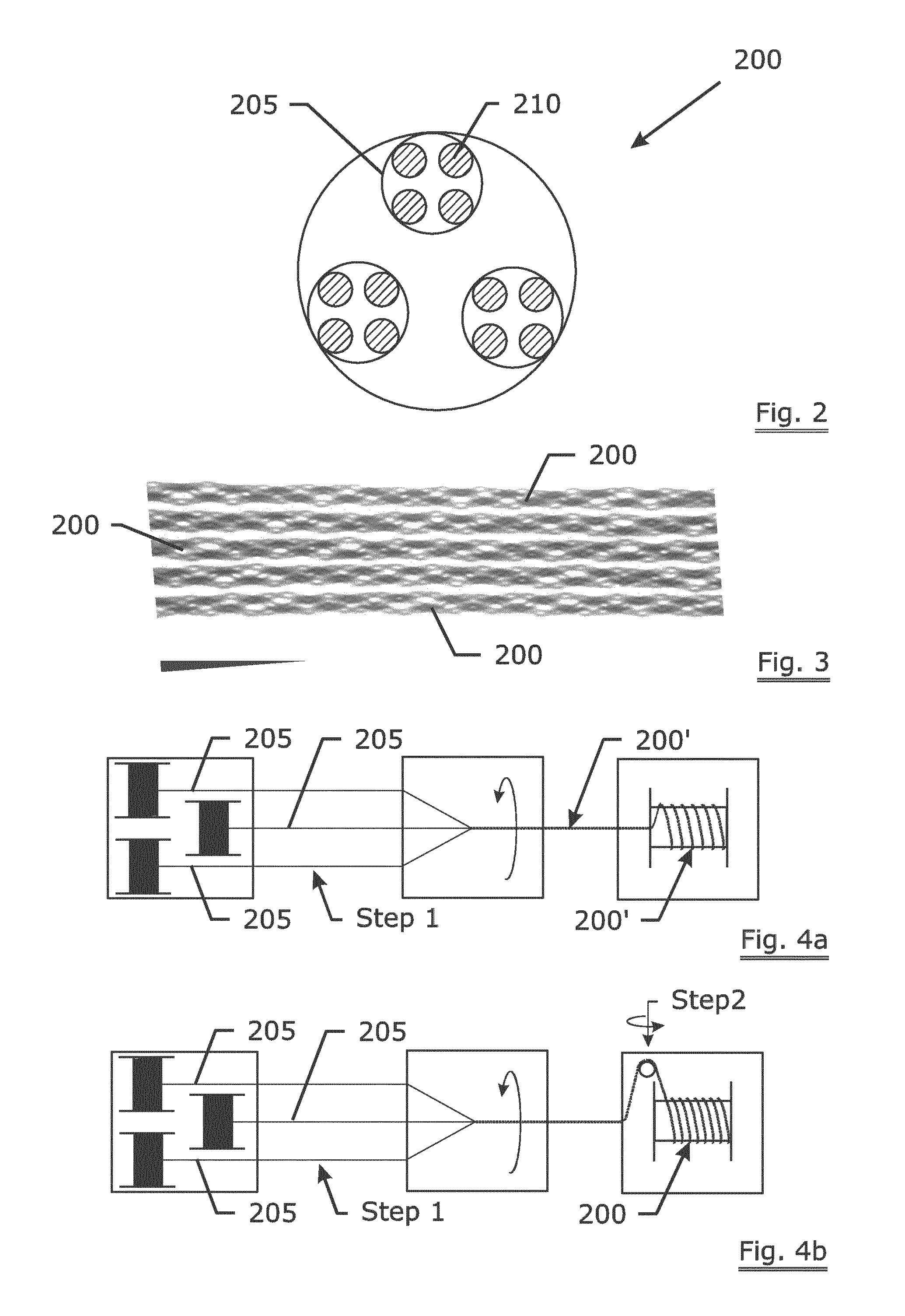
[0035]The prior art steel cord 200′ can be manufactured according to following step. Firstly the four steel filaments 210 are twisted together to form the strand 205, and then the three strands 205 are twisted together according to the step shown in FIG. 4a to form the prior art steel cord 200′, wherein the twist pitch is 8 mm, i.e. 125 twists in one meter length. In present invention, steel strands 205 are twisted together according to the two steps shown in FIG. 4b. The first step is to twist the three steel strand 205 together with the twist pitch 5.33 mm, i.e. 187.5 twists in one meter length. The second step is to give reverse twist at the take-up station to increase the twist pitch to 8 mm, i.e. reverse twist 62.5 rounds in one meter length to achieve the final twist 125 rounds in one meter length. The steel cord 200 incorporating present invention has a strand twist angle 13.62 degree, a cord twist angle 14.72 degree, and the sum of the two twist angles is 28.34 degree (as sh...

second embodiment

[0036]FIG. 5 schematically illustrates the cross-sectional view of a 4×4 steel cord of the The steel cord 500 is a 4×4 structure. The steel cord comprises four steel strands 510 twisted together, and each steel strand 510 comprise four steel filaments 505 twisted together. The diameter of filament 505 is 0.26 mm. The strand twist angle is 14.71 degree, the cord twist angle is 15.89 degree, and the sum of the two twist angles is 30.6 degree.

[0037]Below table 1 shows the comparison test between the embodiments and prior arts.

3 × 4 (prior3 × 44 × 4 (prior4 × 4art)(invention)art)(invention)Strand / cord4.4 / 84.4 / 84.4 / 84.4 / 8twist pitch(mm)Strand twist13.6213.6212.5212.52angle(degree)Cord twist14.7214.7216.4316.43angle(degree)Elongation at4.456.194.786.69break (%)Structural1.352.421.382.97elongation(%)Air pressure700550drop (%)

[0038]As shown in table 1, with the same strand twist angle and cord twist angle, steel cord incorporating present invention has a higher structural elongation and el...

third embodiment

[0041]As present invention, the 5×2 steel cord comprises 5 strands and each strand comprises 2 steel filaments. The filament diameter is 0.26 mm. The strand twist angle is 10.52 degree, the cord twist angle is 19.16 degree, and the sum of the two twist angles is 29.68 degree. The elongation at break of the steel cord is 6.27%, and the structural elongation of the steel cord is 2.78%.


PUM

PropertyMeasurementUnit
Fractionaaaaaaaaaa
Fractionaaaaaaaaaa
Fractionaaaaaaaaaa

Abstract

A steel cord having a plurality of strands twisted together with a cord twist pitch. Each strand having a plurality of filaments twisted together with a strand twist pitch. The elongation at break of the steel cord is no less than 5%. The strand having a strand twist angle. The steel cord having a cord twist angle. When the sum of the strand twist angle and the cord twist angle is between 20 and 29 degree, the structural elongation of the steel cord is no less than 2.0%. When the sum of the strand twist angle and the cord twist angle is between 30 and 38 degree, the structural elongation of the steel cord is no less than 2.5%. When the sum of the strand twist angle and the cord twist angle is between 39 and 48 degree, the structural elongation of the steel cord is no less than 3.0%.

Description

TECHNICAL FIELD[0001]The invention relates to a steel cord, and a pneumatic tire comprising the steel cord.BACKGROUND ART[0002]It is generally known to reinforce rubber products with steel cord, especially for pneumatic tires. The “high elongation” steel cord, as a steel cord, is generally used to reinforce zero degree belt or protection layer of pneumatic tires. Said “high elongation” steel cord refers to steel cord with elongation at break no less than 5%. Elongation at break (δ) is an index of the elasticity of the material. Elongation at break is the percentage ratio between the total elongation ΔL and the original length L of the specimen. δ=ΔL / L×100%. The elongation at break comprises the structural elongation of the steel cord. For example, when a high elongation steel cord is stretched, the extension of the steel cord is firstly the structural elongation. When the steel cord is further stretched, the steel cord may break and result in the elongation at break.[0003]In the tir...

Claims


Application Information

Patent Timeline
IPC IPC(8): B60C9/20B60C9/02B60C9/00D07B1/06D02G3/48
CPCB60C9/2006D07B1/062D02G3/48B60C9/0007B60C2009/2093B60C2009/0092B60C2009/0071B60C2009/2096B60C9/02D07B1/0613D07B3/08D07B7/04D07B2201/1044D07B2201/1076D07B2201/2011D07B2201/2025D07B2201/2029D07B2205/3053D07B2205/3057D07B2205/3071D07B2205/3089D07B2401/201D07B2401/208D07B2207/4031B60C2009/2077B60C2009/209D07B2801/18D07B2801/10B60C2009/2019
Inventor WANG, HEDESPIEGELAERE, ROELZHU, HONGZHEN
Owner NV BEKAERT SA
Why Eureka
Try Eureka