Techniques for modeling elastic rods in position-based dynamics frameworks

a technology of position-based dynamics and rods, applied in the computer field, can solve the problems of quantitative accuracy, pbd frameworks are typically insufficiently represented in animation types, and are unable to simulate complex bending and twisting of objects modeled as rods

Active Publication Date: 2016-06-02
AUTODESK INC
View PDF1 Cites 32 Cited by
  • Summary
  • Abstract
  • Description
  • Claims
  • Application Information

AI Technical Summary

Benefits of technology

[0010]One advantage of the disclosed elastic rod modelling techniques is that these techniques enable the real-time simulation of bending and twisting behavior of elements modelled as rods, such as strands of hair. In particular, simulations may be performed in a position-based dynamics environment, coupling the efficiency inherent in such environments with the realistic modeling of torsion.

Problems solved by technology

Notably, PBD frameworks employ techniques that sacrifice some quantitative accuracy to generate visually plausible results in real-time.
While the tradeoffs exhibited by PBD frameworks are often acceptable, some types of animation are not adequately represented in PBD frameworks.
In particular, because PBD frameworks specify positions but not angles, PBD frameworks are typically unable to simulate complex bending and twisting of objects modeled as rods.
Such a restriction limits the applicability of PBD frameworks to animation.
For example, while PBD frameworks successfully animate much of a human body, PBD frameworks are typically unable to realistically simulate the twisting of curly hair.
While such force-based methods are capable of effectively emulating the natural motion of curly hair, the time required to simulate the thousands of hair strands included in a typical head of hair using force-based methods is prohibitive and unsuitable for animation-oriented applications.

Method used


Image

  • Techniques for modeling elastic rods in position-based dynamics frameworks
  • Techniques for modeling elastic rods in position-based dynamics frameworks
  • Techniques for modeling elastic rods in position-based dynamics frameworks

Examples


Embodiment Construction

[0018]In the following description, numerous specific details are set forth to provide a more thorough understanding of the present invention. However, it will be apparent to one of skilled in the art that the present invention may be practiced without one or more of these specific details.

System Overview

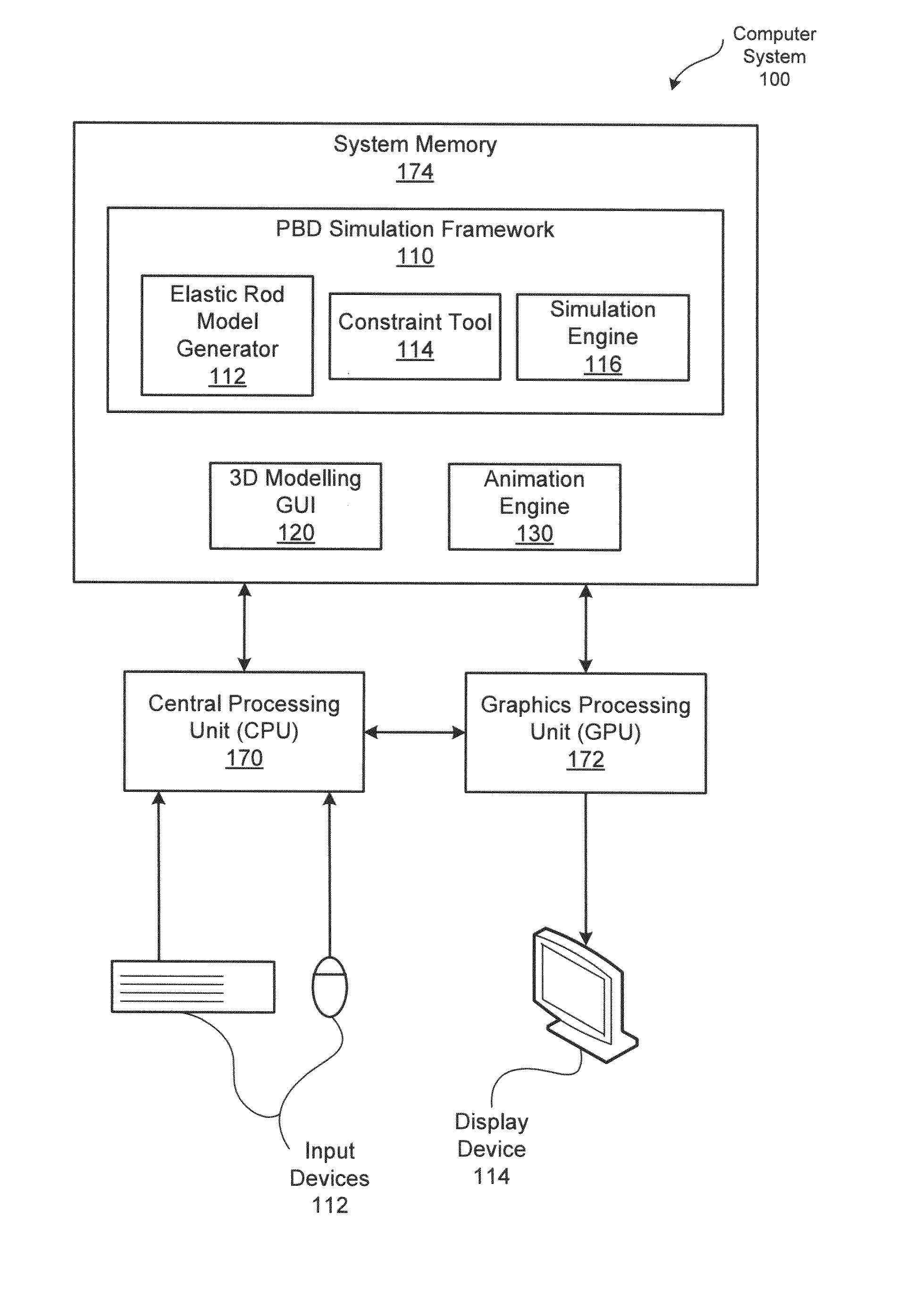
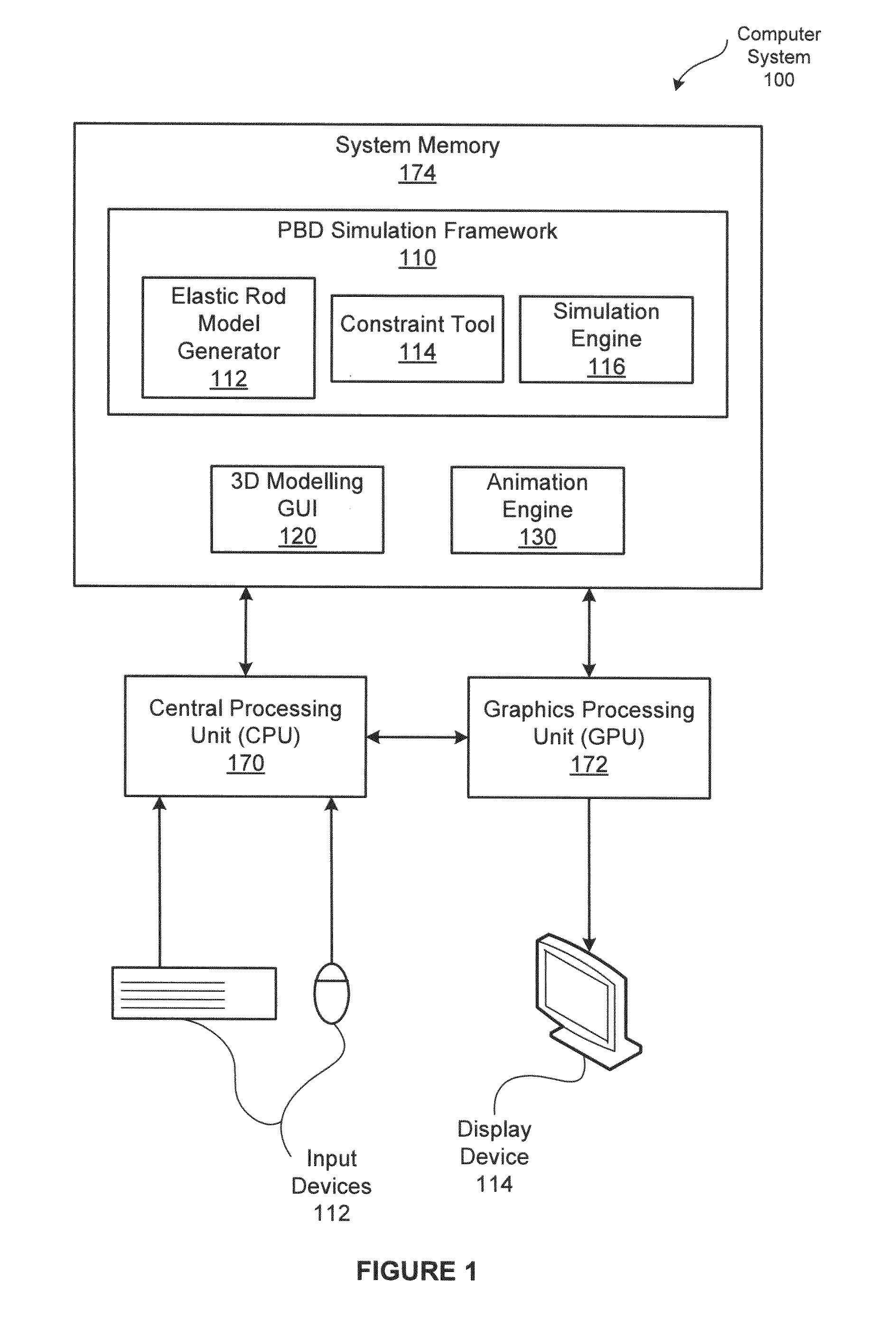
[0019]FIG. 1 is a block diagram illustrating a computer system 100 configured to implement one or more aspects of the present invention. As shown, the computer system 100 includes, without limitation, a central processing unit (CPU) 170, a system memory 174, a graphics processing unit (GPU) 172, input devices 112, and a display device 114.

[0020]The CPU 170 receives input user information from the input devices 112, such as a keyboard or a mouse. In operation, the CPU 170 is the master processor of the computer system 100, controlling and coordinating operations of other system components. In particular, the CPU 170 issues commands that control the operation of the GPU 172. The GPU 1...


PUM


Abstract

In one embodiment of the present invention, a position-based dynamics (PBD) framework provides realistic modeling and simulation for elastic rods. In particular, the twisting and bending physics of elastic rods is incorporated into the PBD framework. In operation, an elastic rod model generator represents the center line of an elastic rod as a polyline of points connected via edges. For each edge, the elastic rod model generator adds a ghost point to define the orientation of a material frame that encodes the twist of the edge. Subsequently, a PBD simulator solves for positions of both points and ghost points that, together, represent the evolving position and torsion of the elastic rod. Advantageously, the ghost points enable more realistic animation of deformable objects (e.g., curly hair) than conventional PBD frameworks. Further, unlike force based methods, elastic rod simulation in the PBD framework performs acceptably in environments where speed is critical.

Description

CROSS-REFERENCE TO RELATED APPLICATIONS[0001]This application claims benefit of the U.S. Provisional Patent Application having Ser. No. 61 / 911,303 (Attorney Docket Number AUTO / 1305USL) and filed on Dec. 3, 2013. This related application is hereby incorporated herein by reference.BACKGROUND OF THE INVENTION[0002]1. Field of the Invention[0003]Embodiments of the present invention relate generally to computer science and, more specifically, to techniques for modelling elastic rods in position-based dynamics frameworks.[0004]2. Description of the Related Art[0005]Generating realistic simulation results in real-time is essential for animating three-dimensional objects in time-sensitive animation applications, such as game engines. Position-based dynamics (PBD) frameworks are well-suited to many such animation applications. Notably, PBD frameworks employ techniques that sacrifice some quantitative accuracy to generate visually plausible results in real-time. For example, in PBD frameworks...

Claims


Application Information

Patent Timeline
Patent Type & Authority Applications(United States)
IPC IPC(8): G06F17/50G06F17/16
CPCG06F17/16G06F17/5009A63F13/57G06F30/20
Inventor SCHMIDT, RYAN MICHAELUMETANI, NOBUYUKISTAM, JOS
Owner AUTODESK INC
Why Eureka
Try Eureka