Walking training system

a training system and walking technology, applied in walking aids, physical therapy, chiropractic devices, etc., can solve the problems of device not being able to detect abnormal states

Active Publication Date: 2016-06-09
TOYOTA JIDOSHA KK
View PDF6 Cites 17 Cited by
  • Summary
  • Abstract
  • Description
  • Claims
  • Application Information

AI Technical Summary

Benefits of technology

[0007]It is an object of the present invention to provide a walking training system that can detect an abnormal state during walking training.

Problems solved by technology

However, the walking rehabilitation device disclosed in Japanese Patent Application Publication No. 2011-50451 (JP 2011-50451 A) has the problem that the device cannot detect the state in which a trainee cannot walk well and walks off the belt.
That is, the problem with the walking rehabilitation device disclosed in Japanese Patent Application Publication No. 2011-50451 (JP 2011-50451 A) is that the device cannot detect an abnormal state that may be generated during walking training.

Method used


Image

  • Walking training system
  • Walking training system
  • Walking training system

Examples


first embodiment

of the Present Invention

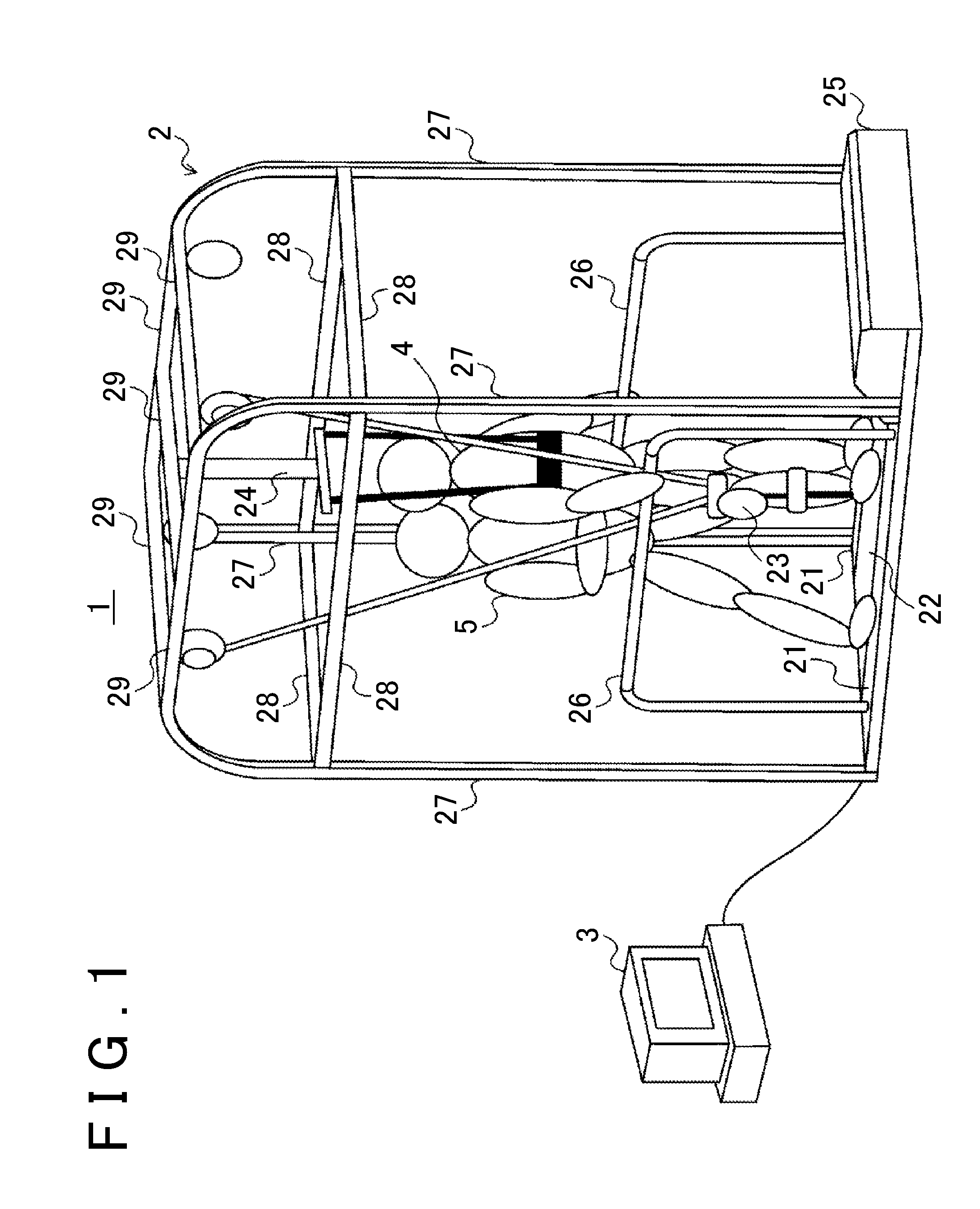
[0054]A first embodiment is described. First, the configuration of a walking training system 1 in the first embodiment is described below with reference to FIG. 1. As shown in FIG. 1, the walking training system 1 includes a treadmill 2 and a control device 3.

[0055]The treadmill 2 is a device on which a trainee 4 conducts walking training. The treadmill 2 functions as a walking training device. The control device 3 is a device that controls the treadmill 2. The control device 3 is typically a Personal Computer (PC). However, the control device 3 is not limited to a personal computer, but other information processing devices, such as a tablet terminal or a smartphone, may also be used.

[0056]The treadmill 2 includes a frame 21, a belt conveyor 22, a robot 23, a relief device 24, a motor box 25, a pair of handrails 26, a plurality of vertical frame components 27, and a plurality of upper frame components 28 and 29.

[0057]The frame 21 is a part on which an assista...

second embodiment

of the Present Invention

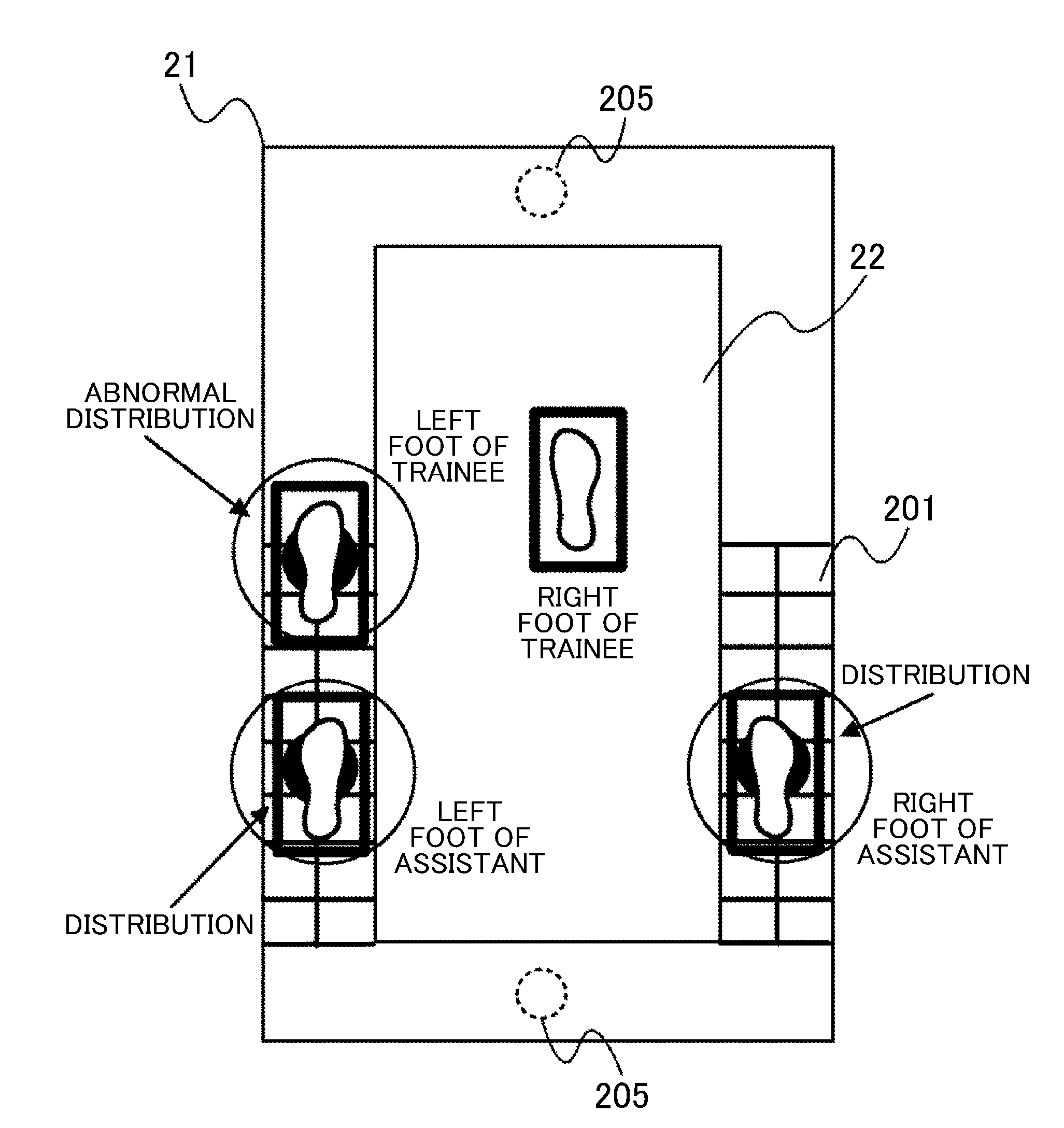
[0110]Next, a second embodiment is described. In the description below, the same contents as those in the first embodiment are omitted as necessary. In the first embodiment, an example is described in which the load sensors 201 are arranged closely to each other in a grid pattern in all the range of the frame 21. However, because the assistant 5 supports the trainee 4 behind the trainee 4 with both hands, the range of the frame 21, in which the assistant 5 places the feet, is limited to a predetermined range on the backward side. In addition, because the trainee 4 is supported by the assistant 5 with both hands, the trainee 4 is positioned very near to the assistant 5. Therefore, when the trainee 4 loses balance and places his or her foot onto the frame 21, the foot of the trainee 4 is very likely to be positioned near to the foot of the assistant 5.

[0111]That is, in the first embodiment, when two load distributions are detected, it is determined whether thos...

third embodiment

of the Present Invention

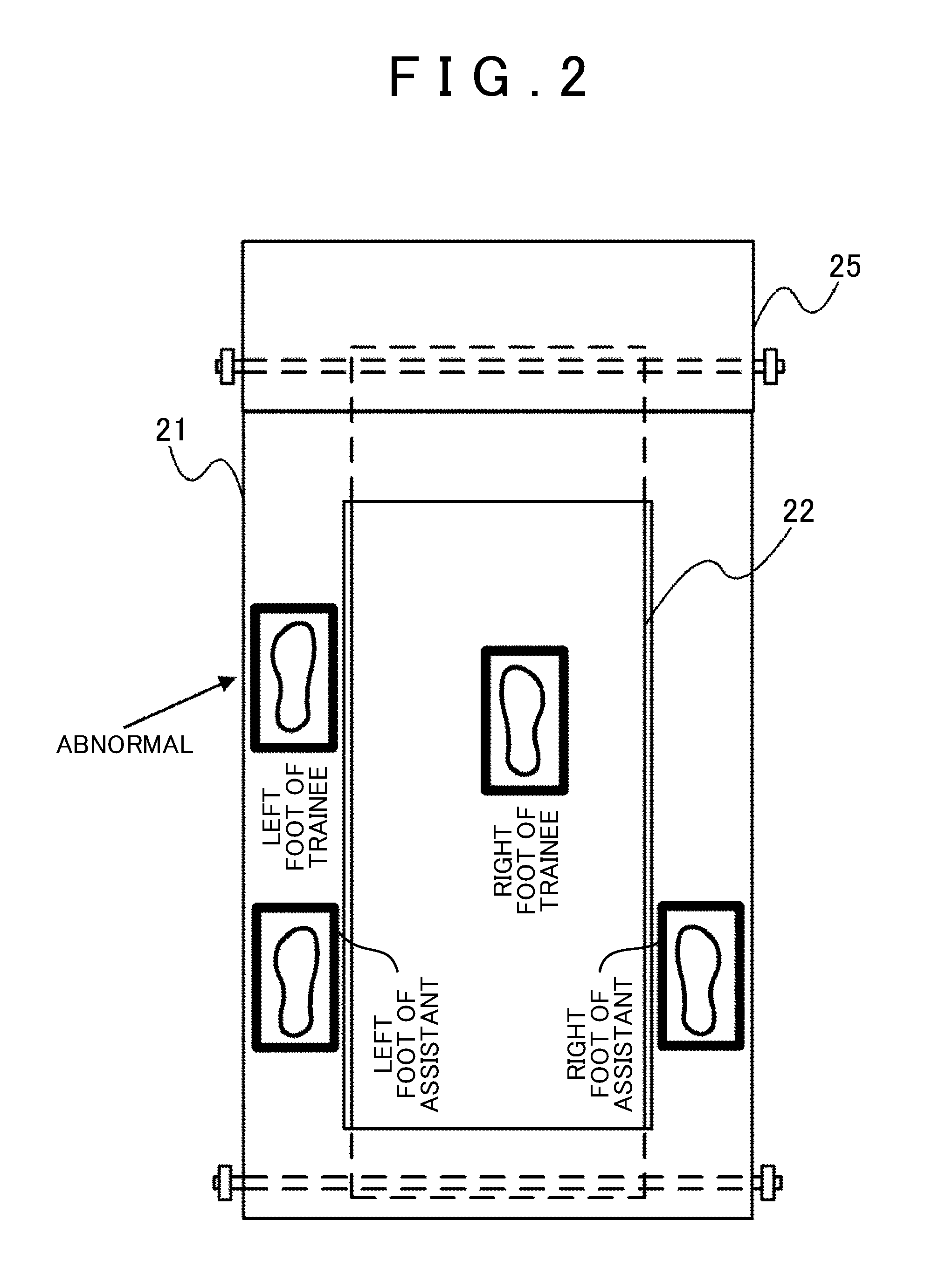
[0124]Next, a third embodiment is described. In the description below, the same contents as those in the first embodiment are omitted as necessary. In the first embodiment, it is determined that an abnormal state is detected if there are three or more feet on the frame 21. However, when the assistant 5 loses balance and steps into the belt conveyor 22, it becomes difficult for the assistant 5 to support the trainee 4 and for the trainee 4 to continue walking training. In the third embodiment, a walking training system 1 that can detect such a condition as an abnormal state is described.

[0125]The third embodiment is different from the first embodiment in that the plurality of load sensors 201 are arranged, not on the frame 21, but on the belt conveyor 22. The load sensors 201 are arranged below the upper belt of the belt conveyor 22. This allows a load to be detected also on the belt that moves. The plurality of load sensors 201 are arranged in a grid pattern ...


PUM


Abstract

A walking training system according to the present invention includes a belt conveyor on which a trainee walks, a frame, a sensor, and a control device. The frame, positioned on both sides of the belt conveyor, allows an assistant to place each of the feet thereon. The sensor measures the presence state of a foot on the frame. The control device determines whether there are three or more feet on the frame based on the measurement result of the sensor and, if it is determined that there are three or more feet, performs abnormal-time control.

Description

INCORPORATION BY REFERENCE[0001]The disclosure of Japanese Patent Application No. 2014-249341 filed on Dec. 9, 2014 including the specification, drawings and abstract is incorporated herein by reference in its entirety.BACKGROUND OF THE INVENTION[0002]1. Field of the Invention[0003]The present invention relates to a walking training system, and more particularly to a walking training system that has a conveyor on which a trainee walks and a pair of frames on which an assistant places the feet, one on each frame.[0004]2. Description of Related Art[0005]Japanese Patent Application Publication No. 2011-50451 (JP 2011-50451 A) discloses a technology that can measure walking data on the walking state during user's walking training without the user having to wear a special measurement apparatus. The walking rehabilitation device disclosed in Japanese Patent Application Publication No. 2011-50451 (JP 2011-50451 A) includes a pair of right and left belts on which the user places the feet. T...

Claims


Application Information

Patent Timeline
Patent Type & Authority Applications(United States)
IPC IPC(8): A63B71/00A63B24/00A63B23/04A63B22/02A63B21/28
CPCA63B71/0054A63B22/02A63B21/285A63B2071/0081A63B24/0062A63B2022/0092A63B23/04A61H3/008A63B22/06A63B24/00A63B69/00A61H2203/0481A61H2203/0406A63B69/0064A63B71/0009A63B24/0087A63B2022/0094A63B2220/52A63B2220/805A63B2220/806A63B2220/807A61H3/00A61H2001/0211
Inventor YAMAZAKI, SEISUKE
Owner TOYOTA JIDOSHA KK
Why Eureka
Try Eureka