
Lower vehicle-body structure of automotive vehicle

a technology for automotive vehicles and body structures, applied in vehicle arrangements, roofs, transportation and packaging, etc., can solve problems such as poor noise performance, improper weight increase, and cabin quietness deterioration, and achieve high rigidity

Active Publication Date: 2016-06-09
MAZDA MOTOR CORP
View PDF4 Cites 64 Cited by
  • Summary
  • Abstract
  • Description
  • Claims
  • Application Information

AI Technical Summary

Benefits of technology

The present invention provides a lower vehicle-body structure that has achieved the desired goal of being lightweight, rigid, and quiet. By using a single cross member between the side sill and the tunnel portion, the vehicle's weight and the reverse phase of mouth opening deformation can be properly attained. Additionally, seat rail mounting seats are provided at the position where reverse-phase deformation occurs, which increases the rigidity of the seat rail against vibration caused by reverse-phase vibration. This prevents twisting of the seat rail and suppresses vibration. Furthermore, the invention also provides a structure that is resistant to twisting of the vehicle body and a tunnel groove to further increase rigidity.

Problems solved by technology

However, since a range where the tunnel portion is not supported at any frame structural body becomes larger, this conventional structure has a problem that a mouth opening deformation of a front-side portion of the single tunnel portion positioned in front of the cross member and a rear-side portion of the tunnel portion positioned in back of the single cross member is improperly enlarged, so that noises may be caused and thereby quietness in a cabin may deteriorate.
However, this long bracket may cause an weight increase improperly despite the above-described weight reduction attained by using the single cross member.
This structure of the patent document has a problem that the mouth opening deformation of the tunnel portion at a position which corresponds to a lower portion of a center pillar becomes so larger, compared to the conventional structure using the two cross members, that the noise performance may deteriorate.

Method used


Image

  • Lower vehicle-body structure of automotive vehicle
  • Lower vehicle-body structure of automotive vehicle
  • Lower vehicle-body structure of automotive vehicle

Examples


Embodiment Construction

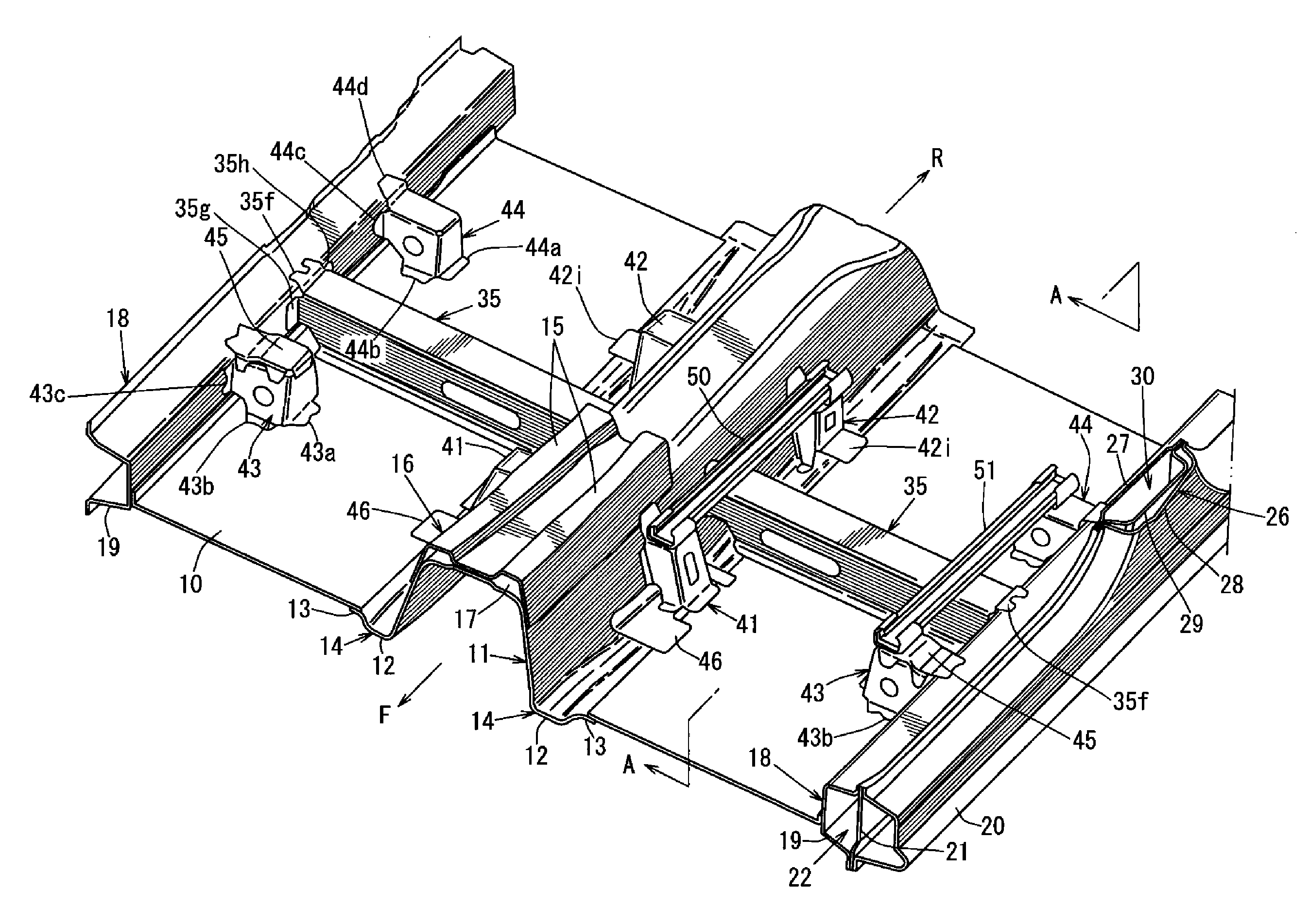
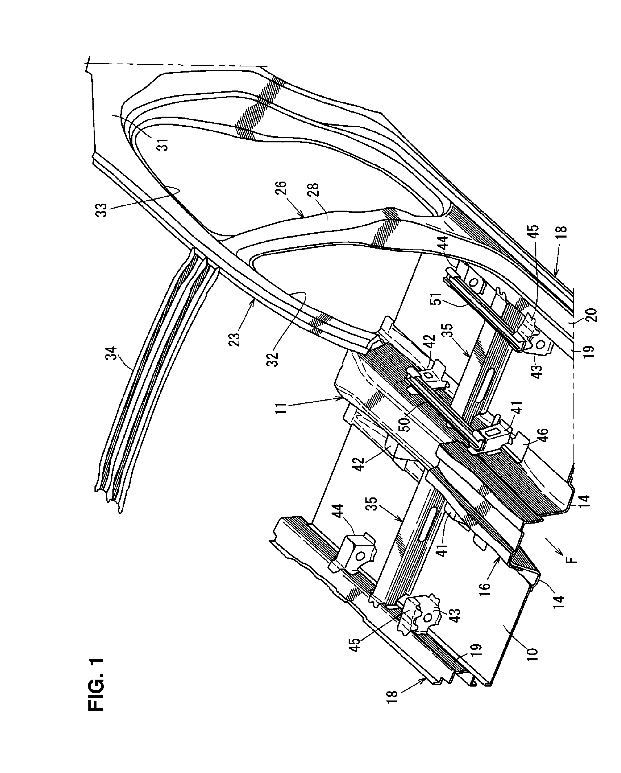
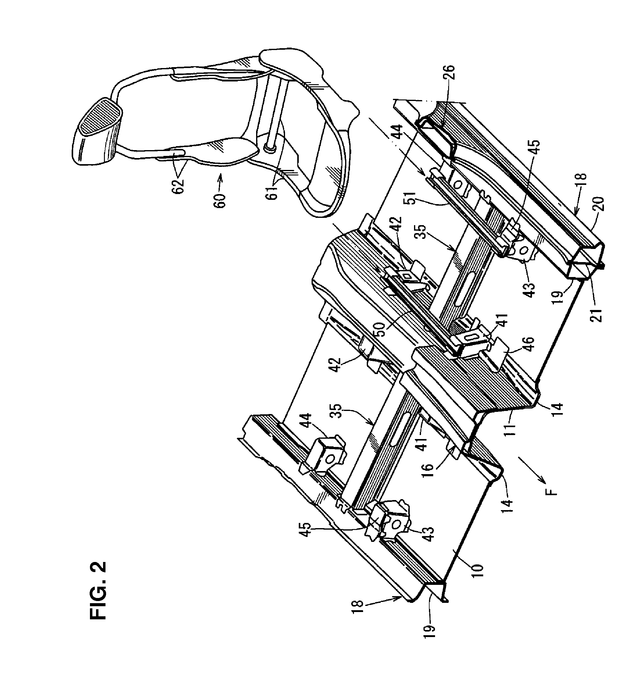
[0025]Hereafter, an embodiment of the present invention will be described referring to the drawings. The drawings show a lower vehicle-body structure of an automotive vehicle. FIG. 1 is a perspective view showing a lower vehicle-body structure of an automotive vehicle of the present invention, FIG. 2 is an exploded perspective view of the lower vehicle-body structure and a seat, FIG. 3 is a major-part enlarged perspective view of FIG. 1, FIG. 4 is an enlarged perspective view of a vehicle-left side of FIG. 3, FIG. 5 is a sectional view taken along line A-A of FIG. 3, and FIG. 6 is a sectional view taken along line B-B of FIG. 5.

[0026]In FIGS. 1, 2 and 3, a floor panel 10 (specifically, a front floor panel) which forms a floor face of a cabin is provided, and a tunnel portion 11 which projects into the cabin and extends in a vehicle longitudinal direction is formed at a central portion, in a vehicle width direction, of the floor panel 10.

[0027]In the present embodiment, the floor pan...


PUM


Abstract

A single cross member extending in a vehicle width direction is provided between a portion of a side sill which is positioned near a center pillar and a tunnel portion. A pair of seat-rail mounting seats are provided at a lower portion of the tunnel portion to be spaced apart from the cross member in a vehicle longitudinal direction. A seat rail is rigidly connected to the pair of seat-rail mounting seats at its bottom face. Thereby, the lightweight, high rigidity, and quietness of the vehicle can be attained.

Description

BACKGROUND OF THE INVENTION[0001]The present invention relates to a lower vehicle-body structure of an automotive vehicle which comprises a tunnel portion provided at a central portion, in a vehicle width direction, of a floor panel and extending in a vehicle longitudinal direction, right-and-left side sills provided at right-and-left both-side portions of the floor panel and extending in the vehicle longitudinal direction, and right-and-left intermediate pillars extending in a vehicle vertical direction from the right-and-left side sills.[0002]In general, a lower vehicle-body structure of an automotive vehicle uses a seat-rail support structure in which a cross member extending in the vehicle width direction is provided between a portion of a side sill which is positioned near a center pillar and a tunnel portion, another cross member is provided in front of the above-described cross member, and a seat rail is supported at the front-and-rear both cross members.[0003]The two cross m...

Claims


Application Information

Patent Timeline
IPC IPC(8): B62D21/15B60N2/005B62D25/20
CPCB62D21/157B60N2/005B62D25/2036B62D25/20B60N2/015
Inventor NAKAYA, KOUICHITAKAHASHI, MUNENARIMORI, MASAKI
Owner MAZDA MOTOR CORP
Learn More