Magnetic toner

a toner and magnetic field technology, applied in the field of electrotrophotography, can solve the problems of difficult to have satisfactory fixability and developability at the same time, prone to external stress, and unable to meet the requirements of low-temperature fixability

Inactive Publication Date: 2016-06-09
CANON KK
View PDF7 Cites 31 Cited by
  • Summary
  • Abstract
  • Description
  • Claims
  • Application Information

AI Technical Summary

Benefits of technology

[0016]According to the present invention, long-term stability, low-temperature fixability and end-portion offset resistance in high-speed printing can be obtained at the sa

Problems solved by technology

However, a toner having satisfactory low-temperature fixability is vulnerable to external stress applied when the toner is stirred in a developer and when the temperature of a developer main-body increases.
Such problems are likely to occur.
However, if the use as mentioned above is presumed, it is difficult to have satisfactory fixability and developability at the same time

Method used


Image

  • Magnetic toner
  • Magnetic toner
  • Magnetic toner

Examples


production examples 2 to 9

of Magnetic Toner Particle

[0292]Magnetic toner particles 2 to 9 were obtained in the same manner as in Production Example 1 except that the type of binder resin in Production Example 1 of a magnetic toner particle was changed to those shown in Table 4. The production conditions and physical properties of magnetic toner particles 2 to 9 are shown in Table 4.

TABLE 4DirectExhaustWeight averagetemperaturetemperatureWeight averagemolecular weight(Rw / Mw)Viscosityof kneadedduring fineparticle diameterat SEC MALLSby SECat 110° C.Binder resinproduct(° C.)grinding(° C.)D4 (μm)(Mw)MALLS(Pa · s)Magnetic toner particle 1St / nBA copolymer 1155387.8100005.5 × 10−315000Magnetic toner particle 2St / nBA copolymer 2160387.855005.0 × 10−310000Magnetic toner particle 3St / nBA copolymer 3150397.8195005.4 × 10−320000Magnetic toner particle 4St / nBA copolymer 4155387.8105003.0 × 10−315000Magnetic toner particle 5St / nBA copolymer 5155387.895006.5 × 10−315000Magnetic toner particle 6St / nBA copolymer 6155387.8110...

production example 1

of Magnetic Toner

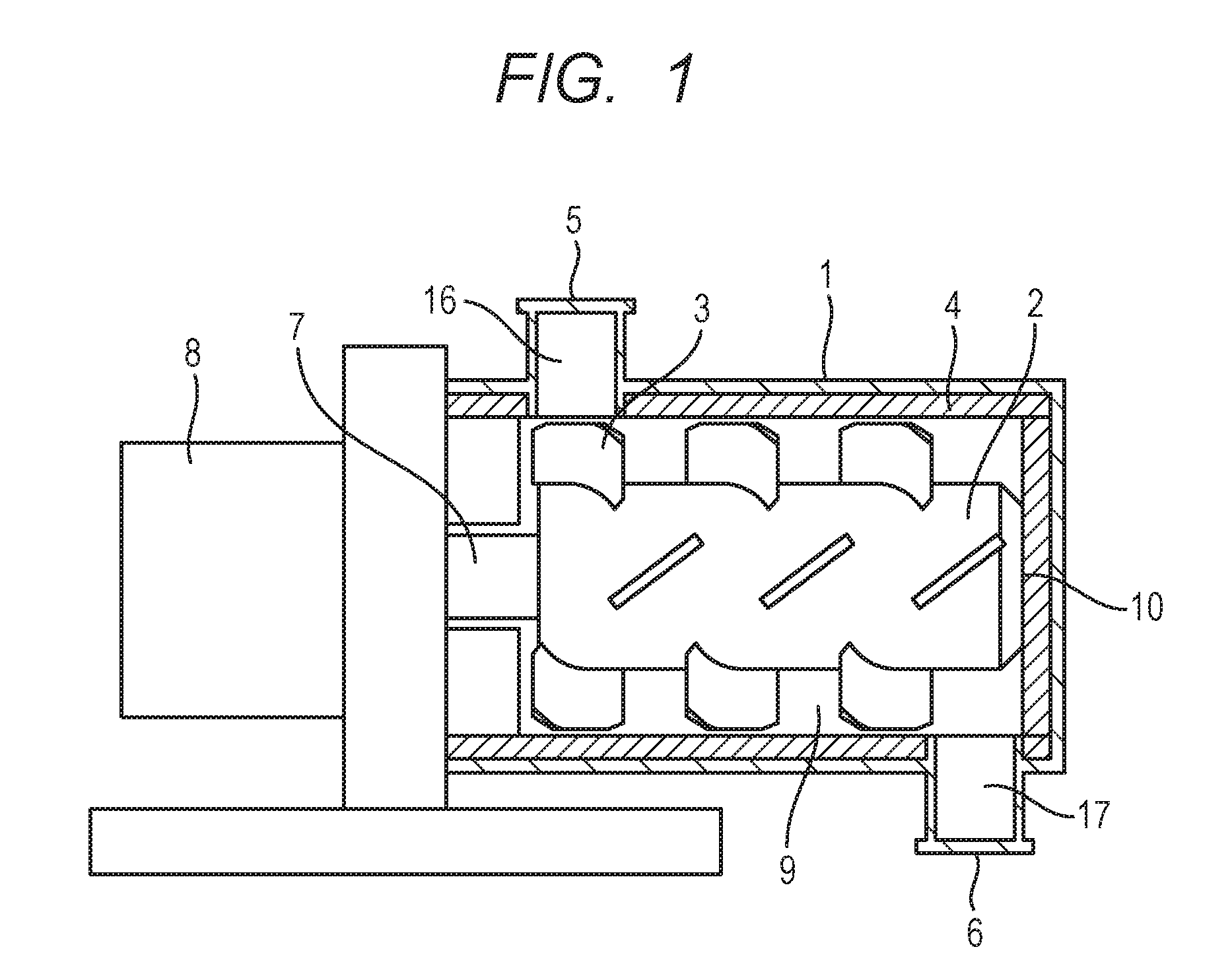
[0293]To magnetic toner particle 1 obtained in Production Example 1 of magnetic toner particle, external additives was added by using the apparatus shown in FIG. 1.

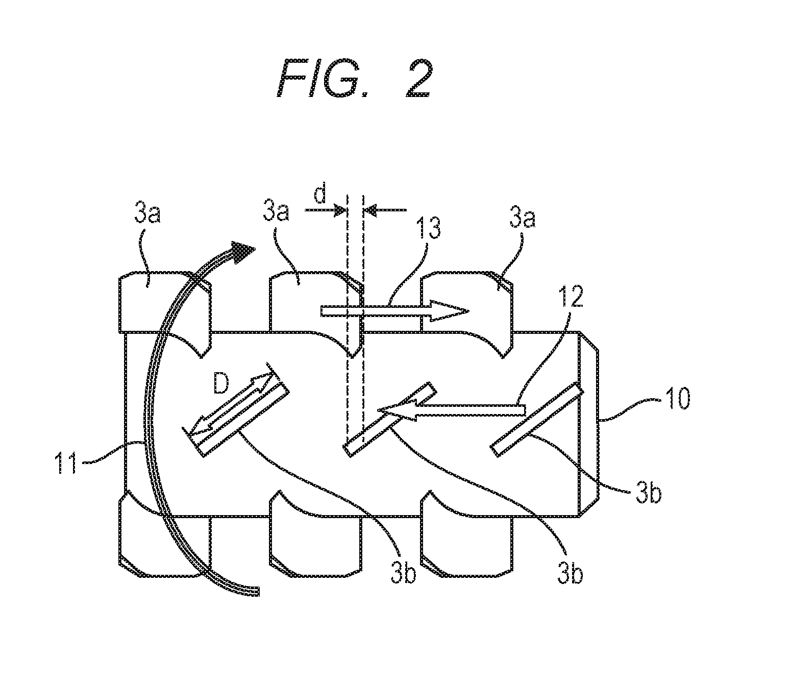
[0294]In this Example, the apparatus shown in FIG. 1 (the inner periphery diameter of main-body casing 1: 130 mm, the volume of a treatment space 9: 2.0×10⁻³ m3) was used. The rated power of a driving portion 8 was set at 5.5 kW. The shape of a stirring member 3 as shown in FIG. 2 was used. In FIG. 2, the width d of overlapped portion of a stirring member 3a with a stirring member 3b was set at 0.25D where D represents a maximum width of the stirring member 3, and the clearance between the stirring member 3 and the inner circumference of the main body casing 1 was set at 3.0 mm.

[0295]To the apparatus shown in FIG. 1 having the aforementioned constitution, the magnetic toner particle 1 (100 parts) and additives shown in Table 5 were placed.

[0296]Silica fine particle 1 was obtained by treating 100 parts of ...

examples 2 to 10

[0318]Toners 2 to 10 were prepared in the same manner as Example 1 according to the formulations shown in Table 5. The values of the physical properties of the toners thus obtained are shown in Table 6. The same test as above were performed and the results are shown in Table 7.


PUM

PropertyMeasurementUnit
Temperatureaaaaaaaaaa
Fractionaaaaaaaaaa
Fractionaaaaaaaaaa

Abstract

A magnetic toner comprising a toner particle containing a styrene resin as a binder resin and a magnetic substance, and a first inorganic fine particle on surface of the toner particle and an organic-inorganic composite fine particle on the surface of the toner particle, wherein the first inorganic fine particle i) contains at least one inorganic oxide fine particle selected from the group consisting of silica fine particle, titanium oxide fine particle and alumina fine particle, with the proviso that the inorganic oxide fine particle contains silica fine particle in an amount of 85 mass % or more based on the total mass of the inorganic oxide fine particle, and ii) has a number-average particle diameter (D1) of 5 nm or more and 25 nm or less, the coverage ratio A of the toner-particle surface with the first inorganic fine particle is 45.0% or more and 70.0% or less.

Description

TECHNICAL FIELD[0001]The present invention relates to electrophotography, an image forming method for visualizing an electrostatic image and a magnetic toner for use in a toner jet.BACKGROUND ART[0002]It has been strongly desired that image forming apparatuses employing electrophotography method are operated at a higher speed with higher reliability. In addition, the apparatuses are highly required to consume less energy. To satisfy these requirements, a toner is highly demanded to have excellent low-temperature fixability. The low-temperature fixability of a toner is generally related to the viscosity thereof, and the property of being melted quickly by heat during fixation (so-called the sharp-melting properties) is required. However, a toner having satisfactory low-temperature fixability is vulnerable to external stress applied when the toner is stirred in a developer and when the temperature of a developer main-body increases. As a result, embedment of an external additive(s) oc...

Claims


Application Information

Patent Timeline
IPC IPC(8): G03G9/097
CPCG03G9/09725G03G9/081G03G9/083G03G9/0833G03G9/08708G03G9/08795G03G9/09716
Inventor YAMAZAKI, KATSUHISANISHIKAWA, KOJIYOSHIBA, DAISUKENOMURA, SHOTAROAKIYAMA, HIROKIFUJIMOTO, MASAMI
Owner CANON KK
Why Eureka
Try Eureka