Wireless controller including indicator

a technology of indicator and wireless controller, which is applied in the direction of data switching network, wireless commuication services, instruments, etc., can solve the problems of difficult application of internet of things technologies to existing home appliances released, and things technologies developed

Active Publication Date: 2016-06-09
SAMSUNG ELECTRONICS CO LTD
View PDF7 Cites 34 Cited by
  • Summary
  • Abstract
  • Description
  • Claims
  • Application Information

AI Technical Summary

Benefits of technology

[0030]According to another embodiment, a method of controlling an external device using a hardware-based controller having a movable indicator may be provided. The method may include recognizing an input voice command using the controller, selecting a motion from a plurality of motions that the indicator is configured to perform, the indicator being configured to appear like a natural object, associating the selected motion with the recognized voice command and controlling the indicator to perform the selected motion, thereby indicating that the voice command has been recognized, and generating, using the controller, a control signal to control the external device to perform a task that corresponds to the recognized input voice command.
[0031]According to an embodiment, a wireless controller for controlling an external device may include a voice recognizer to recognize an input voice command, a movable indicator configured to appear like a natural object, a hardware-based controller to select a motion from a plurality of motions that the indicator is configured to perform, to associate the selected motion with the recognized voice command, and to control the indicator to perform the selected motion, thereby indicating that the voice command has been recognized, and a communication unit to generate a control signal to control the external device to perform a task that corresponds to the recognized input voice command.

Problems solved by technology

However, it is difficult to apply Internet of Things technologies to existing home appliances which were released or sold before the Internet of Things technologies were developed.

Method used


Image

  • Wireless controller including indicator
  • Wireless controller including indicator
  • Wireless controller including indicator

Examples


first embodiment

[0117]An indicator according to the present disclosure will be described with reference to the drawings.

[0118]As illustrated in FIGS. 19 to 22, an indicator 1 according to the first embodiment of the present disclosure includes a flowerpot 10, a pair of stems 11 and 12 vertically movably installed at the flowerpot 10, a pair of flowers 13 and 14 blooming by interlocking with the vertical movement of the pair of stems 11 and 12, a driving device 15 generating a power, and a lifting device 16 receiving the power from the driving device 15 to lift the stems 11 and 12, wherein the driving device 15 and the lifting device 16 are accommodated in the flowerpot 10.

[0119]The first flower 13 and the second flower 14 both remain closed as illustrated in FIG. 19 and FIG. 22 when the stems 11 and 12 have moved downward, and as the stems 11 and 12 rise, only the first flower 13 blooms as illustrated in FIG. 20 and FIG. 23, and then the first flower 13 and the second flower 14 both bloom as illust...

second embodiment

[0147]Hereinafter, an indicator according to the present disclosure will be described in detail with reference to the drawings.

[0148]In the present embodiment, as illustrated in FIG. 27 and FIG. 28, an indicator 2 is applied to a water storage unit 3 used in a humidifier, and the like, and is able to display a water level of water filled in the water storage unit 3.

[0149]The water storage unit 3 includes a water bottle 31 of which a top surface is open to fill water therein, and a water bottle cover 32 covering the top surface of the water bottle 31.

[0150]The indicator 2 includes a stem 21 vertically movably installed at the water bottle cover 32, a flower 22 installed at the top of the stem 21, and a buoyant body 23 installed at the bottom of the stem 21. In the present embodiment, as illustrated in FIG. 29, the five indicators 2 include five stems 21 disposed apart from each other in a circumferential direction, five flowers 22 respectively installed at tops of the five stems 21, ...

third embodiment

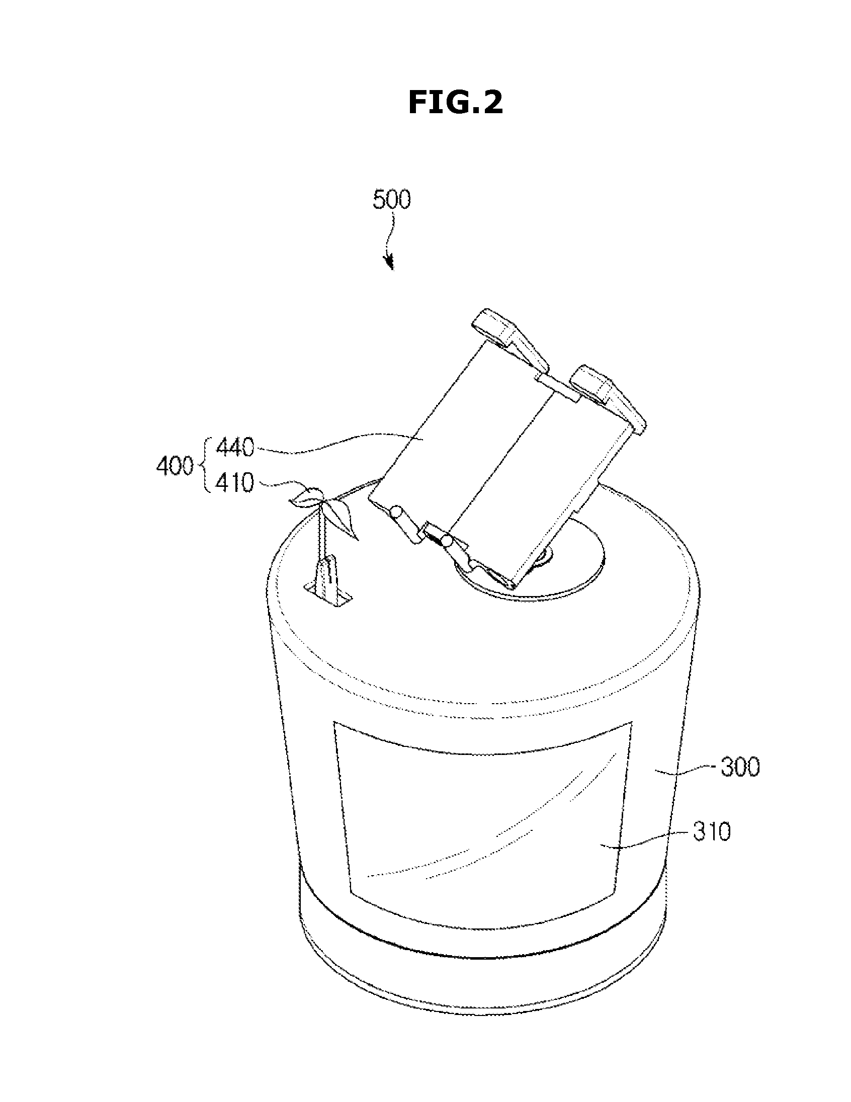
[0163]As illustrated in FIG. 34, an indicator 4 according to the present disclosure may include boughs 44 instead of flowers.

[0164]In the present embodiment, the indicator 4 includes a flowerpot 41, a plurality of stems 42 vertically disposed on the flowerpot 41 in order, and a plurality of joints 43 disposed between the stems 42 to enable the stems 42 to be rotatably coupled to each other, wherein the stems 42 include the boughs 44 branched out and extending from the stems 42.

[0165]The stems 42 and the boughs 44 are formed of light guiding members of a transparent or semi-transparent material to guide light, and a light source (not shown) such as a light-emitting diode is included in the joints 43 to supply light to the stems 42 and the boughs 44.

[0166]Consequently, by supplying the light though the light source from the stem 42 positioned at a lower side to the stem 42 positioned at an upper side in order as a condition value transmitted to the indicator 4 becomes closer to the op...


PUM


Abstract

Embodiments disclosed herein provide a wireless controller which shows a voice, motion, or an image complying with or not complying with a user's command and controls an external device in accordance with the user's command. According to an embodiment, a wireless controller includes a main body provided in a shape of a flowerpot, and includes a voice recognition unit, a control unit generating a signal for controlling an object to be controlled, which is designated by a voice recognized in the voice recognition unit, in accordance with the voice, and a communication unit outputting the control signal generated in the control unit to the object to be controlled; and an indicator provided at the main body in a shape of at least one of a stem, a leaf, a flower, and a tree, and showing a motion corresponding to the voice recognized in the voice recognition unit.

Description

CROSS-REFERENCE TO RELATED APPLICATIONS[0001]This application claims the benefit of Korean Patent Application Nos. 10-2014-0171972 filed on Dec. 3, 2014 and 10-2015-0135151 filed on Sep. 24, 2015 in the Korean Intellectual Property Office, the disclosures of which are incorporated herein by reference.BACKGROUND[0002]1. Field[0003]The present disclosure relates to a wireless controller which remotely controls an external device.[0004]2. Description of the Related Art[0005]Recently, technologies related to the Internet of Things are being developed. However, it is difficult to apply Internet of Things technologies to existing home appliances which were released or sold before the Internet of Things technologies were developed. Recently, attempts to apply the Internet of Things technologies to existing home appliances are being made.SUMMARY[0006]Embodiments disclosed herein provide a wireless controller that shows whether or not a voice, motion, or an image comply with a user's command...

Claims


Application Information

Patent Timeline
Patent Type & Authority Applications(United States)
IPC IPC(8): G10L15/22H04W4/00H04L12/24G06F3/16H04W4/60H04W4/80
CPCG10L15/22G06F3/167H04W4/003G10L2015/223H04L41/22G10L2015/221H04W4/008H04L12/2803H04L67/12H04W4/60H04W4/80H04L12/2816
Inventor CHOI, SANG HWAKIM, BO KYUNGSEO, JI HOLEE, CHANG WOOK
Owner SAMSUNG ELECTRONICS CO LTD
Why Eureka
Try Eureka