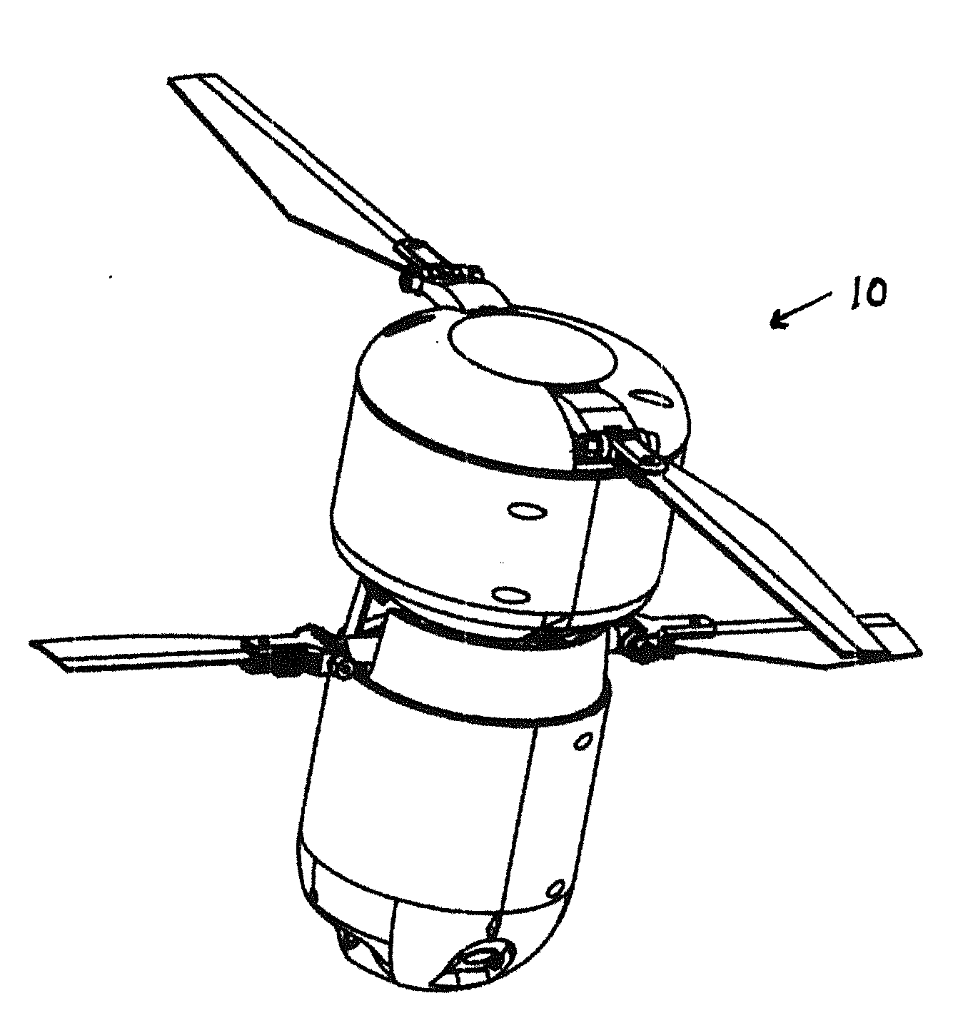
Unmanned Flying Device

a flying device and unmanned technology, applied in the field of unmanned flying devices, can solve the problems of less than desirable storage and/or landing position of the rotor blade, prone to damage and/or injury of persons, etc., and achieve the effects of convenient and practical use, high manufacturing cost, and compact structur

Active Publication Date: 2016-06-16
ASCENT AEROSYST INC
View PDF0 Cites 76 Cited by
  • Summary
  • Abstract
  • Description
  • Claims
  • Application Information

AI Technical Summary

Benefits of technology

[0006]It is yet another objective of the present invention to provide an improved unmanned flying device construction that can be utilized for a variety of applications, including aerial surveillance, amusement (e.g. toy helicopters), and the delivery of items.
[0007]It is yet another objective of the present invention to provide an improved unmanned flying device construction that can overcome the bulky and awkward designs, fragile blades,

Problems solved by technology

On the other hand, others have appeared to recognize that always maintaining the rotor blades in a deployed position is less than desirable for storage

Method used


Image

  • Unmanned Flying Device
  • Unmanned Flying Device
  • Unmanned Flying Device

Examples


Embodiment Construction

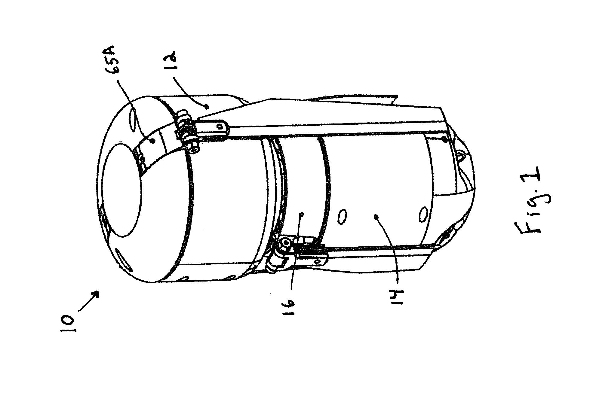
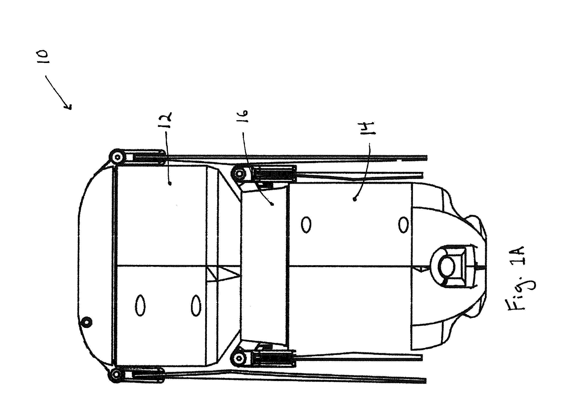
[0032]Generally speaking, the present invention is directed to embodiments of unmanned flying devices all having compact constructions capable of leveraging their overhead position or perspective to aid a user or group. The preferred embodiments of unmanned flying devices as set forth herein are preferably sized to be convenient for a single person to carry by hand or in a bag or case, but larger embodiments are contemplated depending on the desired application.

[0033]The preferred embodiments all preferably comprise a coaxial rotor design preferably comprising a pair of rotors aligned on a central axis. Embodiments including other rotor configurations including a quadcopter or multicopter configurations are also contemplated herein. Each rotor preferably comprises two or more aerodynamic blades, which provide propulsive lift when spun. While and when not spinning, these aerodynamic blades automatically fold, collapse or retract along the body of the unmanned flying device to, among ...


PUM


Abstract

An unmanned flying device including a body; a first blade and at least a second blade; a coupling assembly for coupling the first blade and the at least second blade to the body, wherein the coupling assembly urges the collapsing of the first blade and the at least second blade towards the body; and wherein both the first blade and the at least second blade are rotatable about the body, and wherein the first blade and the at least second blade are deployable away from the body via rotation of the first and the at least second blades about the body.

Description

CROSS REFERENCE TO RELATED APPLICATION[0001]This application claims the benefit of U.S. Application Ser. No. 62 / 077,783 filed on Nov. 10, 2014. The subject matter of said provisional application is incorporated by reference as if fully set forth herein.BACKGROUND OF THE INVENTION[0002]The present invention is directed to unmanned flying devices, and in particular, to an unmanned flying device construction that provides for a collapsing or folding of the device's rotor blades upon a decrease or absence of rotor blade rotation about the device's body and for the deployment of the rotor blades away from the device's body upon a rotation thereof about the device's body. Such a construction, among other things, assists in preventing or minimizing damage to the device during a landing without the need for landing gear or other structure that may otherwise perform the function thereof.[0003]Unmanned flying devices, also commonly referred to as “drones,” are well-known and becoming more pop...

Claims


Application Information

Patent Timeline
IPC IPC(8): B64C27/37B64C39/02B64C27/10
CPCB64C27/37B64C27/10B64C2201/18B64C2201/108B64C39/024B64C27/50B64U30/12B64U10/10B64U30/20B64C27/006B64U70/00B64U30/293B64U30/24
Inventor MERINGER, JONATHAN R.MERINGER, NATHANIEL R.
Owner ASCENT AEROSYST INC
Why Eureka
Try Eureka