Sensor device with mounting means

a technology of mounting means and sensors, applied in the field of sensors, can solve the problems of increasing the distance between the sensor system and the required location, destroying the assembly and components, and unable to find suitable locations for the required sensor system, so as to facilitate the use of retrofit applications, avoid the installation of wires or cables, and improve the chance of detection

Active Publication Date: 2016-06-16
AB SKF
View PDF2 Cites 4 Cited by
  • Summary
  • Abstract
  • Description
  • Claims
  • Application Information

AI Technical Summary

Benefits of technology

[0009]The bracket of the sensor device according to the invention ensures that the sensors can be aligned for optimal detection. The second portion of the bracket arranged upright is configured for mounting the sensors and preferably has a flat surface. The coupling of acoustic emission and vibrations is of high quality because acoustic waves entering the bracket via the first portion can be securely guided to the second portion and the sensor. The angled arrangement of the two portions leads to a compact design while at the same time allowing for the insertion of a screw or bolt and fixing tools to tighten the screw or bolt even within very restricted space limits.
[0019]Further, it is proposed that a signal processing device is formed as a PCB which is potted or overmoulded in order to protect the electronics from vibration, temperature, fire, foreign object strike corrosion, etc. The electronic parts should fulfil the standards set, e.g., in EN50155 and EN61373.

Problems solved by technology

When attempting to monitor the condition, it is often difficult to find suitable locations for the required sensor systems such that they can be applied without disassembly of mechanical systems and resultant destruction of the assemblies and components they are intended to monitor.
However, increased mounting comfort often leads to an increased distance between the sensor system and the component of interest, such that the quality of the measurement is reduced due to attenuation, increased noise and environmental factors.
The longer the transmission path for heat or acoustic waves, the higher the risk that information gets lost.

Method used


Image

  • Sensor device with mounting means
  • Sensor device with mounting means
  • Sensor device with mounting means

Examples


Embodiment Construction

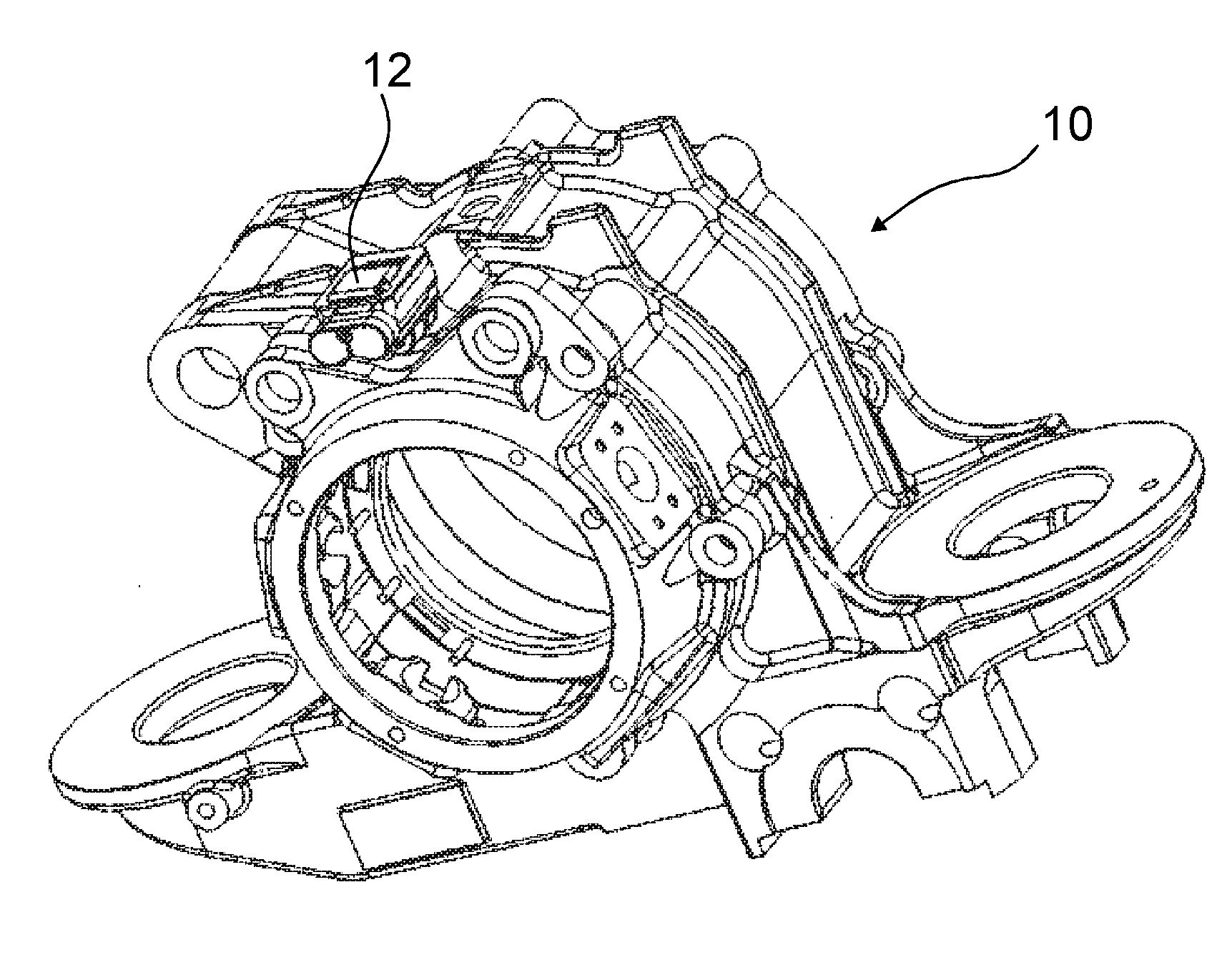
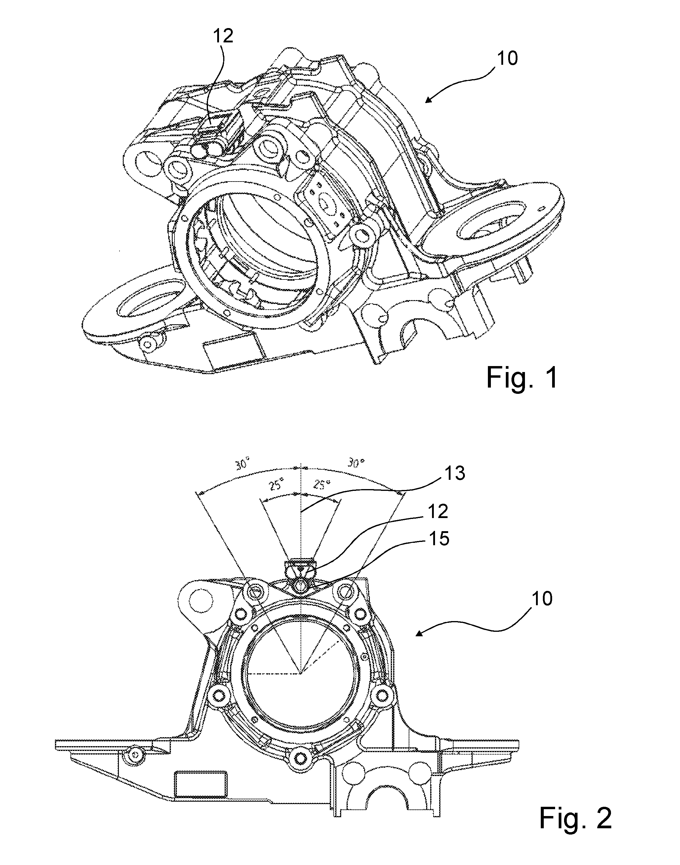
[0035]FIG. 1 illustrates an axle box 10 for a passenger train comprising a central bore 10a for receiving a double-row roller bearing (not shown). A sensor device 12 according to the invention is attached to a flange in a top part of the axle box 10.

[0036]As illustrated in FIG. 2, the sensor device 12 is attached directly in the line of load 13 of the axle box 10 and of the bearing mounted therein such that the sensor device 12 is located very close to a loaded zone of the bearing in a direction of maximum stiffness of the axle box 10. The sensor device includes a bolt 15 for fastening a body part of the sensor device 12 to the axle box. The mounting position maximizes the transmission of high frequency noise as generated e.g. by defects of the rolling elements passing by the sensor device 12.

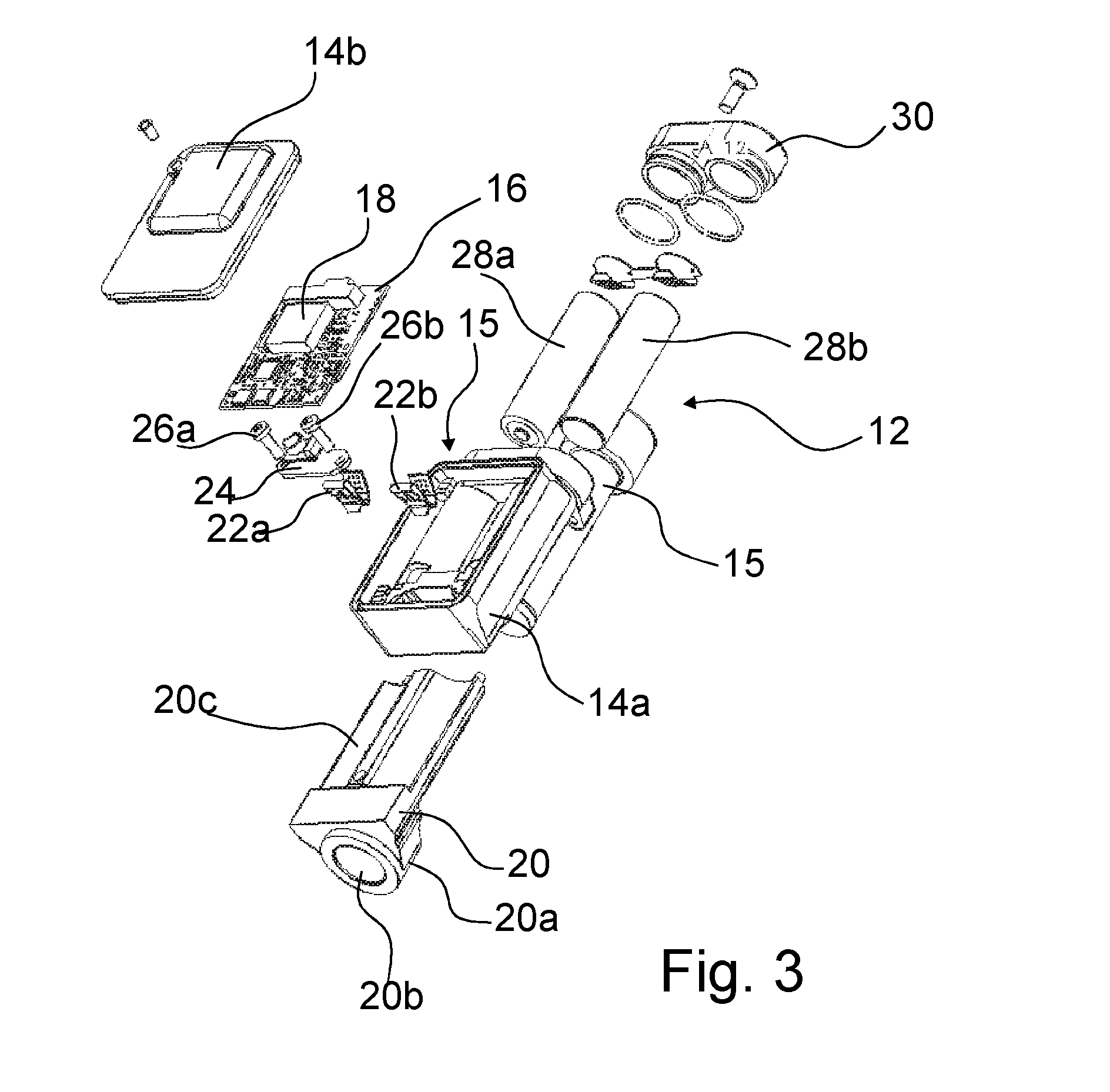
[0037]FIG. 3 is an exploded view of the sensor device 12 according to the invention. The sensor device 12 comprises a housing 14 having a lower housing part 14a and a housing cover part 14b, bo...


PUM

PropertyMeasurementUnit
clamping forceaaaaaaaaaa
transmissionaaaaaaaaaa
rigidityaaaaaaaaaa

Abstract

A sensor device for monitoring a component of interest, including at least one sensor for measuring at least one parameter indicative of condition of the component of interest, signal processing device for processing the signals of the sensor, a housing for at least the signal processing device and a mounting feature for mounting the sensor device close to the component of interest. The mounting feature can include a bolt and bracket having a first portion including an opening for inserting the bolt in an insertion direction and a second portion with a surface parallel to the insertion direction configured to mount the housing.

Description

CROSS REFERENCE TO RELATED APPLICATION[0001]This is a Non-Provisional Patent Application, filed under the Paris Convention, claiming the benefit of Great Britain (GB) Patent Application Number 1421781.4, filed on 8 Dec. 2014 (08.12.2014), which is incorporated herein by reference in its entirety.FIELD OF THE INVENTION[0002]The invention relates to a sensor device for monitoring a mechanical component of interest, in particular a train bearing arranged in a train axle box.BACKGROUND OF THE INVENTION[0003]The invention relates to devices for monitoring the condition of components, in particular of rotating components of vehicles or machinery. When attempting to monitor the condition, it is often difficult to find suitable locations for the required sensor systems such that they can be applied without disassembly of mechanical systems and resultant destruction of the assemblies and components they are intended to monitor.[0004]Sensor systems should be configured such that they can be q...

Claims


Application Information

Patent Timeline
Patent Type & Authority Applications(United States)
IPC IPC(8): F16C19/52
CPCF16C19/525F16C19/527G01M13/04G01M13/045G01D5/00G01D11/00B61F15/20F16C19/522G01D11/02G01D11/30G01K1/16G01H1/003G01H3/00F16C2326/10F16C41/00F16C2233/00F16C2204/50F16C2220/02B60B27/00B61L15/0081G01D11/245
Inventor CAMPBELL, ANDREWTHOMSON, ALLAN
Owner AB SKF
Why Eureka
Try Eureka