
Shock Pump Adapter

a technology for shock pumps and adapters, which is applied in the direction of shock absorbers, screw threaded joints, functional valve types, etc., can solve the problems of not having a design that allows and cannot avoid structural interference, and achieve the effect of avoiding structural interference and connecting to the pump head

Inactive Publication Date: 2016-06-16
WU SCOTT
View PDF0 Cites 4 Cited by
  • Summary
  • Abstract
  • Description
  • Claims
  • Application Information

AI Technical Summary

Benefits of technology

The present invention provides a shock pump adapter that can easily connect a shock absorber without interfering with its function. It can also engage with an air pumping device and a shock absorber without interfering with their structures. This improves the overall performance of the shock pump system.

Problems solved by technology

Nevertheless, the pump head does not have a design that allows a shock absorber to be connected thereto easily nor can avoid structural interfere with the shock absorber during inflation.

Method used


Image

  • Shock Pump Adapter
  • Shock Pump Adapter
  • Shock Pump Adapter

Examples


first embodiment

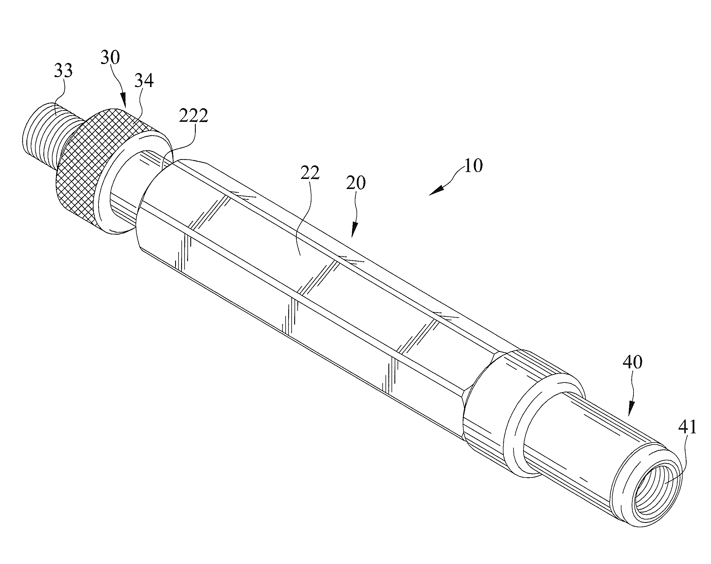
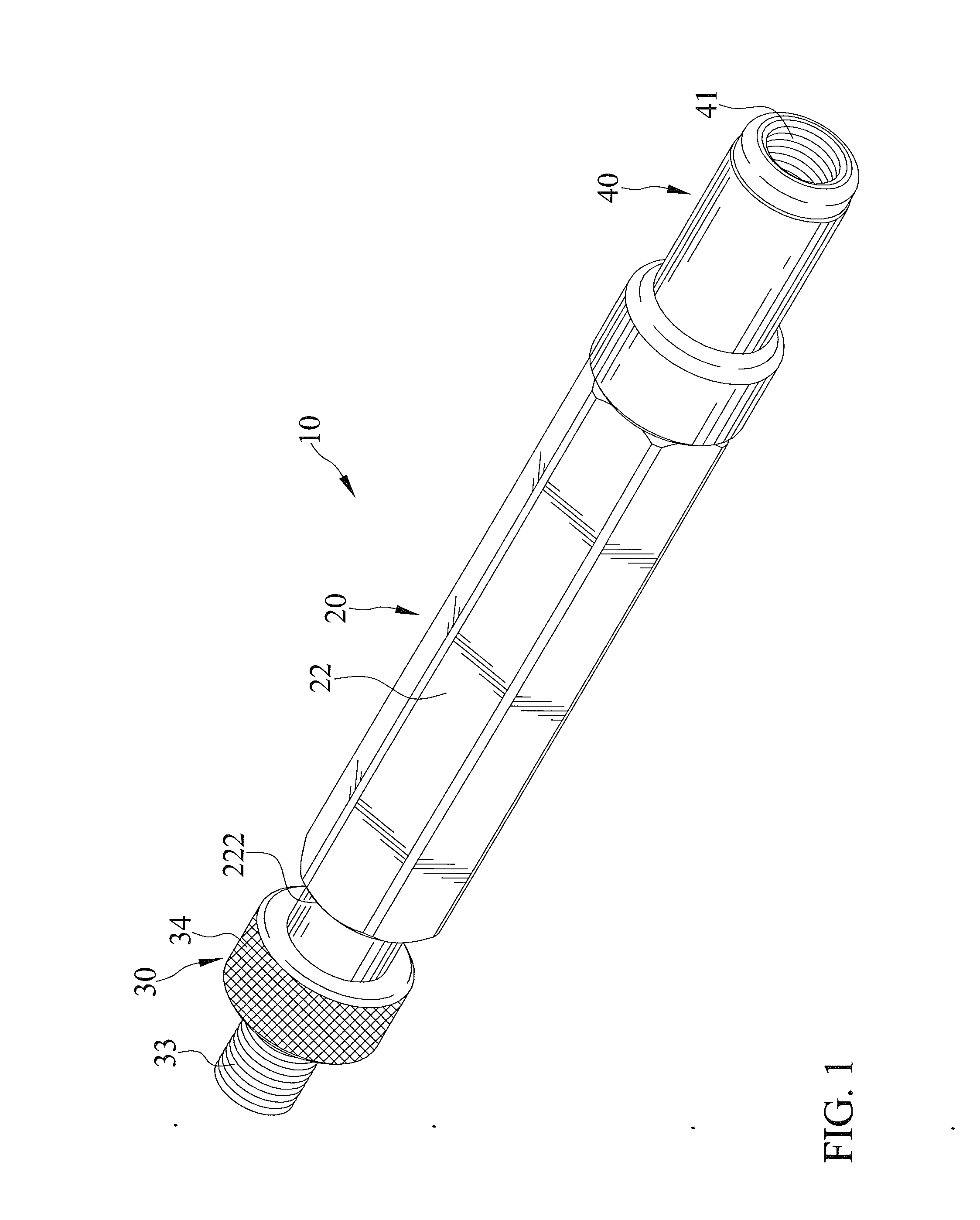
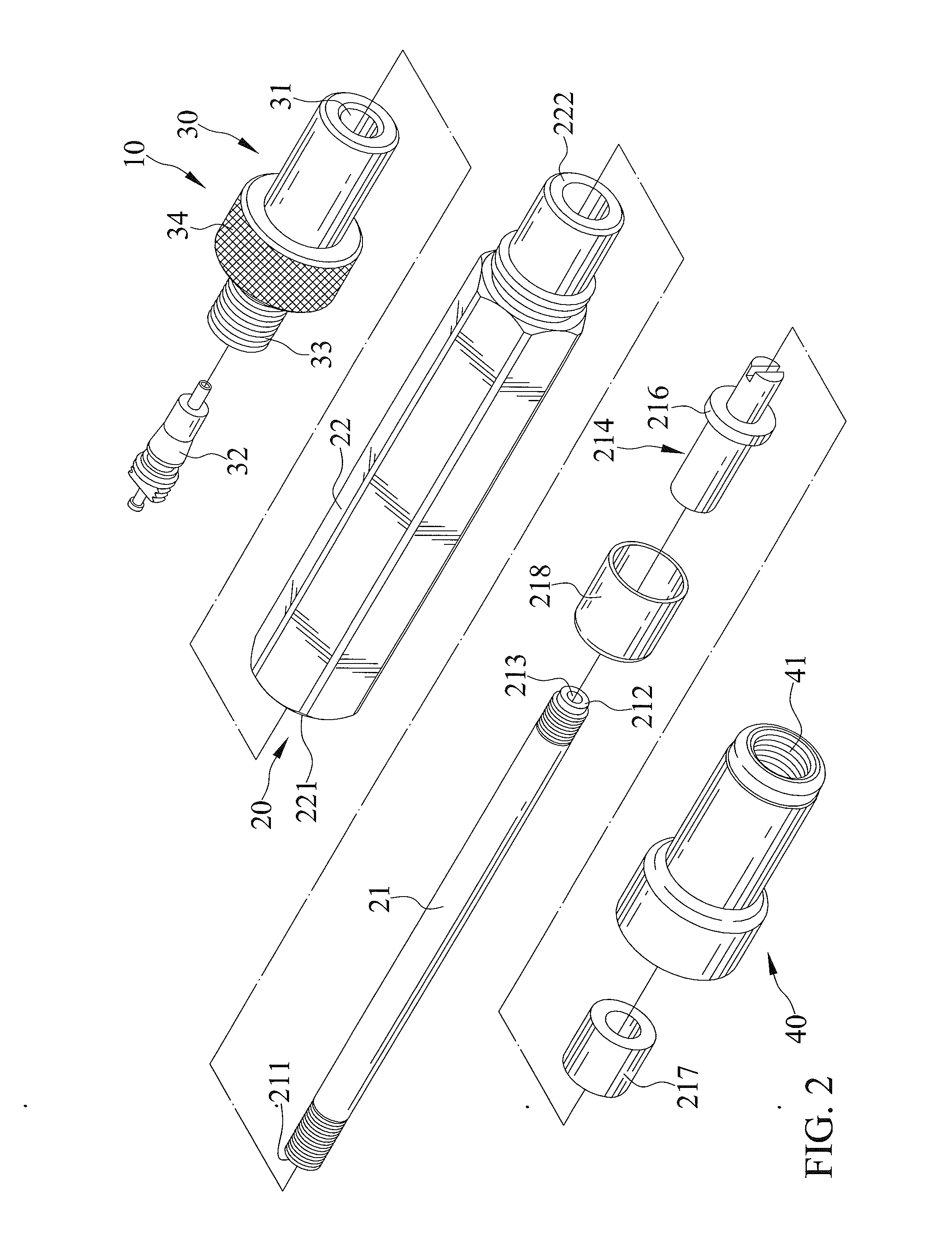
[0019]FIGS. 1 through 3 show a shock pump adapter 10 in accordance with the present invention. The shock pump adapter 10 includes a communication device 20, a valve insert 214, an air inlet joint 30, and an air outlet joint 40.

[0020]The communication device 20 is configured to include an inner tube 21 and an outer tube 22. The inner tube 21 has a first end 211 and a second end 212 opposite the first end 211 and has a longitudinal length between the first and second ends 211 and 212 thereof. The outer tube 22 has a first end 221 and a second end 222 opposite the first end 221 and has a longitudinal length between the first and second ends 221 and 222 thereof The inner tube 21 is disposed within a hollow of the outer tube 22. The hollow of the outer tube 22 has a first section having a first cross section and a second section having a second cross section. The second cross section of the second hollow section of the outer tube 22 is greater than the first cross section of the first ho...

second embodiment

[0029]FIGS. 4 and 5 show a shock pump adapter 10a in accordance with the present invention. The shock pump adapter 10a is the same as the shock pump adapter 10 except that an inner tube 24a and a valve insert 214a are of one-piece construction and made from the same material. Therefore, the inner tube 21a and the valve insert 214a are not subject to separating from one another inadvertently.

[0030]In view of the foregoing, the air inlet joint 30 is rotatable with the inner tube 21 or 21a and the air outlet joint 40 is rotatable with the outer tube 22 and the inner tube 21 is rotatable relative to the outer tube 22. Therefore, when the air pumping device with the air inlet joint 30 are rotatably engaged together, it is still easy and free to rotatably engage the shock absorber with the air outlet joint 40. In addition, the valve inserts 214 and 214a is rotatable with the associated inner tubes 21 and 21a engaged therewith.


PUM


Abstract

A shock pump adapter includes a communication device configured to include an inner tube and an outer tube. The inner and outer tubes are rotatable with respect to one another. A valve insert fixes to one of two ends of and is rotatable with the inner tube and includes a first channel fluidly connecting to a hollow of the inner tube. An air inlet joint fixes to the other of the two ends of and is rotatable with the inner tube. The air inlet joint includes a second channel fluidly connecting to the hollow of the inner tube and a one-way valve disposed in the second channel. An air outlet joint connects to and is disposed at the other of the two ends of the communication device. The air outlet joint fixes to and is rotatable with the outer tube.

Description

BACKGROUND OF THE INVENTION[0001]1. Field of the Invention[0002]The present invention relates to a pump adapter and, particularly to a shock pump adapter.[0003]2. Description of the Related Art[0004]TW Patent Publication No. TW201319433 shows a pump head of a pump. The pump head includes a housing, a sleeve, and a valve insert. The sleeve is disposed in the housing. The valve insert is disposed in the sleeve. In addition, the valve insert is configured to include different valve abutting ends for engagement with different types of valves. The pump head is adapted to connect to a shock absorber. Alternatively, the pump head is adapted to connect to a tire. Therefore, it is convenient for a user to use such a dualfunctional device to selectively inflate a shock absorber or a tire. Nevertheless, the pump head does not have a design that allows a shock absorber to be connected thereto easily nor can avoid structural interfere with the shock absorber during inflation.[0005]The present in...

Claims


Application Information

Patent Timeline
IPC IPC(8): F16L15/08F16F9/43F16L29/00
CPCF16L15/08Y10T137/3724F16F9/43F16L29/007
Inventor WU, SCOTT
Owner WU SCOTT
Learn More