
Centrifuge Feed Accelerator with Feed Vanes

a technology of centrifuge feed and accelerator, which is applied in the direction of centrifuges, rotary centrifuges, etc., can solve the problems of affecting the efficiency of centrifuges, so as to achieve the effect of reducing the number of shear forces

Inactive Publication Date: 2016-06-23
APD HLDG
View PDF1 Cites 0 Cited by
  • Summary
  • Abstract
  • Description
  • Claims
  • Application Information

AI Technical Summary

Benefits of technology

The invention relates to a device that helps to accelerate and distribute material in a centrifugal separator more efficiently, with minimal damage to the material. This device can be added on to existing separators and is easy to use. Its technical effects include improved speed and accuracy of separation and reduced damage to the material.

Problems solved by technology

The loading and acceleration process can damage sensitive chemical or biological substances such as intact cells or proteins.
Heterogeneities in the distribution of feed material within the separator bowl may arise, however, and add shear stresses as the material mixes with the contents of the bowl.
These factors can reduce the efficiency of separation and degrade the biological activity of the material.

Method used


Image

  • Centrifuge Feed Accelerator with Feed Vanes
  • Centrifuge Feed Accelerator with Feed Vanes
  • Centrifuge Feed Accelerator with Feed Vanes

Examples


Embodiment Construction

[0018]The present invention now will be described more fully hereinafter with reference to the accompanying drawings, in which illustrative embodiments of the invention are shown. In the drawings, the relative sizes of regions or features may be exaggerated for clarity. This invention may, however, be embodied in many different forms and should not be construed as limited to the embodiments set forth herein; rather, these embodiments are provided so that this disclosure will be thorough and complete, and will fully convey the scope of the invention to those skilled in the art.

[0019]It will be understood that when an element is referred to as being “coupled” or “connected” to another element, it can be directly coupled or connected to the other element or intervening elements may also be present. In contrast, when an element is referred to as being “directly coupled” or “directly connected” to another element, there are no intervening elements present. Like numbers refer to like elem...


PUM


Abstract

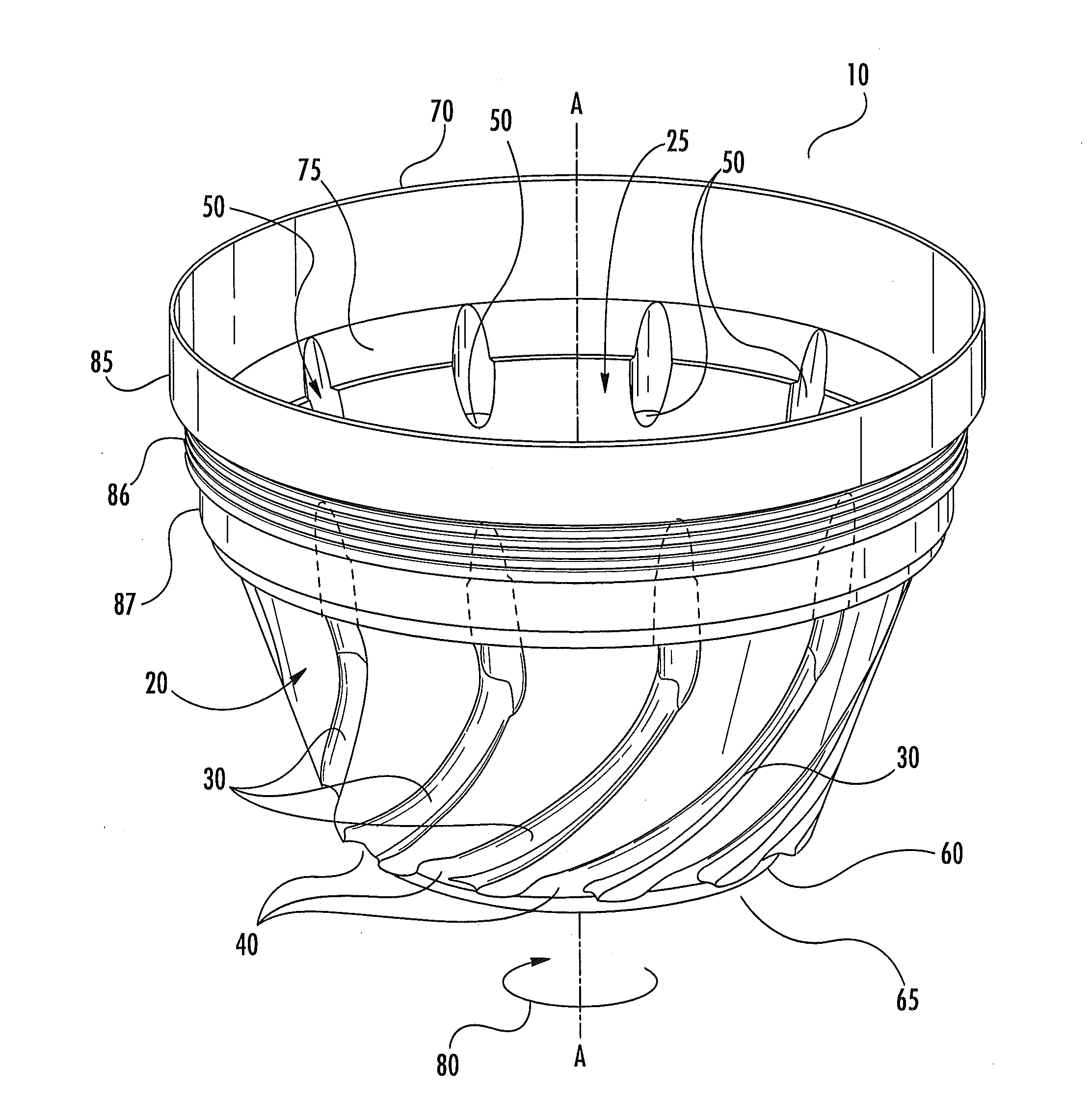
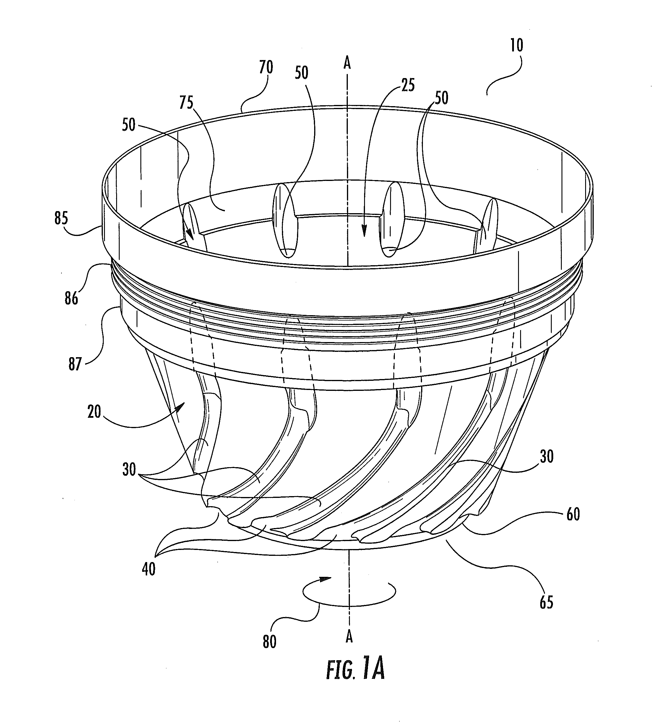
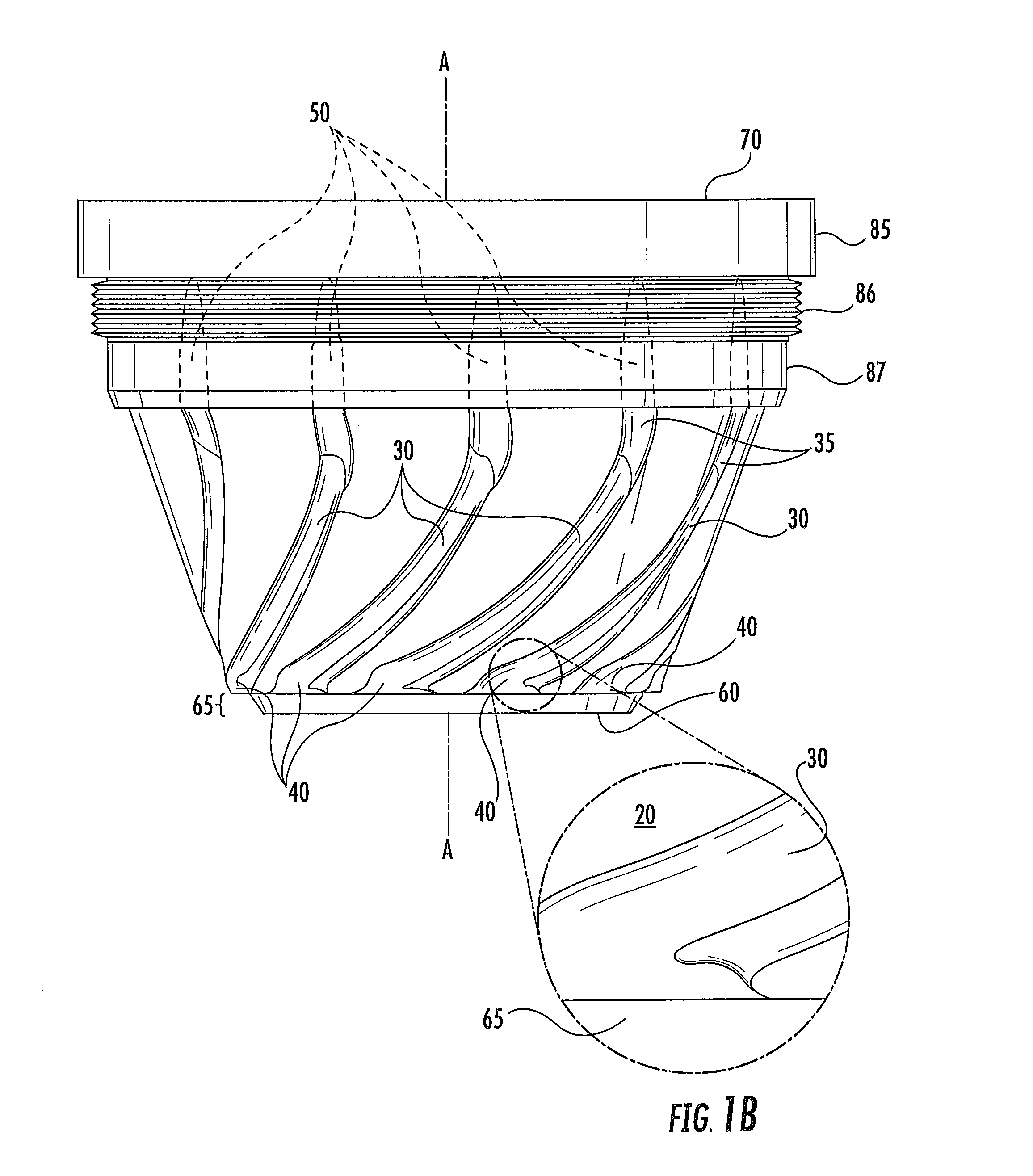
A feed accelerator for a centrifugal separator includes a set of vanes or grooves built into its outer surface to define a plurality of channels. Channel openings at the bottom of the accelerator face in the direction of rotation, and the channels curve upwards, aligning with the rotation axis at the top of the accelerator, so as to accelerate the feed liquid from bottom to top of the accelerator. The entry and exit points of the channels are positioned within smoothening zones that promote a circumferentially homogeneous distribution of the feed material. The purpose of this device is to provide minimal shear forces on the channel entrances to minimize shear stress on the feed liquid which can contain fragile solids in suspension. It is intended to be used primarily in automatic piston discharge liquid / solid centrifugal separators.

Description

RELATED APPLICATION[0001]This application claims priority from U.S. Provisional Application No. 61 / 863,067, filed Aug. 7, 2013, the disclosure of which is hereby incorporated herein in its entirety.BACKGROUND OF THE INVENTION[0002]Centrifugal separators are used for separating heterogeneous mixtures into components based on their specific gravity. A heterogeneous liquid mixture, or feed liquid, is injected into a rotating bowl of a centrifugal separator. The rotating bowl spins at high speed, forcing components of high specific gravity to sediment. As a result, dense solids compress to form a cake or paste against the wall of the bowl, and clarified liquid, or centrate, forms radially inward from the cake. The bowl can spin at speeds sufficient to create an acceleration of 20,000 times the force of gravity, causing separation of the solids from the rest of the feed liquid. As solids accumulate along the wall of the bowl, the centrate exits from the bowl and leaves the separator. In ...

Claims


Application Information

Patent Timeline
Patent Type & Authority Applications(United States)
IPC IPC(8): B04B7/08
CPCB04B7/08B04B1/00B04B11/06
Inventor ZHENG, JIECARR, ROBERT B.
Owner APD HLDG
Learn More