Vascular closure methods and apparatuses

a technology of vascular closure and vascular valve, which is applied in the field of vascular closure methods and apparatuses, can solve the problems of high rate of post-puncture hemorrhage, large number of steps, and considerable complications, and achieve the effects of preventing intravascular preventing the migration of the device, and keeping tension on the wound

Inactive Publication Date: 2007-03-15
ABBOTT CARDIOVASCULAR
View PDF69 Cites 211 Cited by
  • Summary
  • Abstract
  • Description
  • Claims
  • Application Information

AI Technical Summary

Benefits of technology

[0011] The present invention can provide a catheter-delivered umbrella-like device comprising fine, strong, flexible material that after delivery expands in a blood vessel so that the individual members extend beyond the catheter edges and / or puncture dimensions. The device can be viewed as analagous in structure and design as contemporary expandable vascular filters and closure umbrellas, although its purpose and function is completely different. As the catheter is withdrawn, the device is pulled against the interior of the blood vessel and the hooks or grasping devices on the ends of the members seize the interior of the vessel wall. Because of the very fine and flexible nature of the members and their multiplicity, there is minimal shear force applied to the blood vessel. While pulling on the retaining suture to keep the device against the blood vessel, a retaining lock is then advanced distally starting at the proximal portion of the members, which causes the members to first angle the device into a conical shape and then force the individual members together in a linear parallel direction, which because the members are engaged with the vessel wall, brings the edges of the punctured tissue together into apposition. The retainer lock is then locked onto the parallel members and can keep tension on the wound externally, and can prevent intravascular migration of the device. If there is no blood leakage through the closure and the device is properly positioned and stable, then the guidewire can be removed and the retaining suture or string loop cut, resulting is complete and rapid closure, which can then heal.
[0012] Since this device brings the puncture edges together, there is true blood vessel healing with little endothelial disruption, reducing the chances of thrombosis or intimal hyperplasia. The device can be supplied in different diameters (e.g., french) to accommodate different sizes of catheters and different sizes of puncture holes.

Problems solved by technology

With conventional methods, the rate of post-puncture hemorrhage is high, which causes considerable complications.
Difficulties with these methods include the large number of steps necessary to deploy the needles, capture the suture, withdraw the suture, tie the knot, and cut the suture.
In addition, the hole in the blood vessel is often widened by insertion of the instrument, and the suture remains intravascularly on the endothelial surface, and thus can be a nidus for thrombus or intravascular mural hyperplasia with later spontaneous and catastrophic closure of the vessel.
Disadvantages to these methods are related to the high likelihood of thrombosis associated with the intravascular plug or anchor, and the presence of collagen or other bioabsorble materials which cause inflammation, activate the clotting cascade, and increase the likelihood of thrombosis, which, in an arterial system, is catastrophic.
These are generally impractical for catheter-based methods.
This also requires a complicated device, and perforation and thrombosis are very real possibilities.
These clip devices are composed of thick semi-rigid material, and can be placed only with a specialized instruments, and because of the rigidity have great potential to injure or cut the blood vessel.
Disadvantages of these clip devices in general include difficulty in retrieving the device if misplaced, excessive manipulation required, the thickness of the clip material which tends to cut or shear the blood vessel, the large forces that must be used to curve the staples and fix the clips, the increased possibility of tearing the blood vessel, and the general lack of control of the forces being applied to the blood vessel.

Method used


Image

  • Vascular closure methods and apparatuses
  • Vascular closure methods and apparatuses
  • Vascular closure methods and apparatuses

Examples


example embodiments

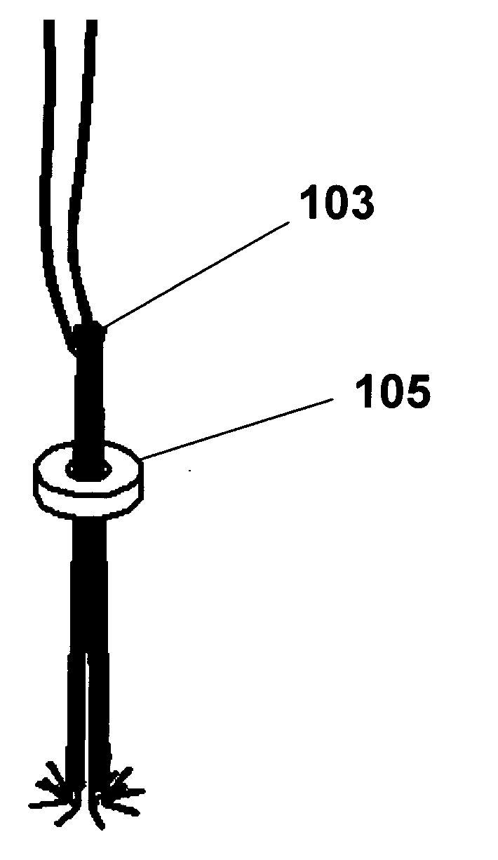
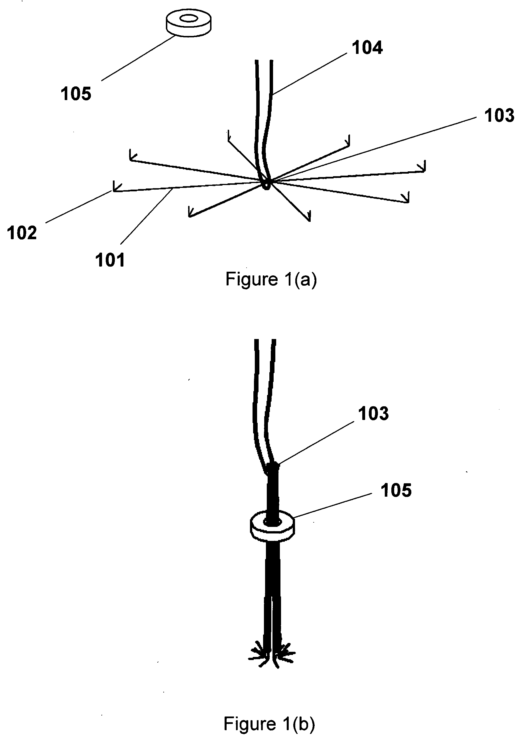
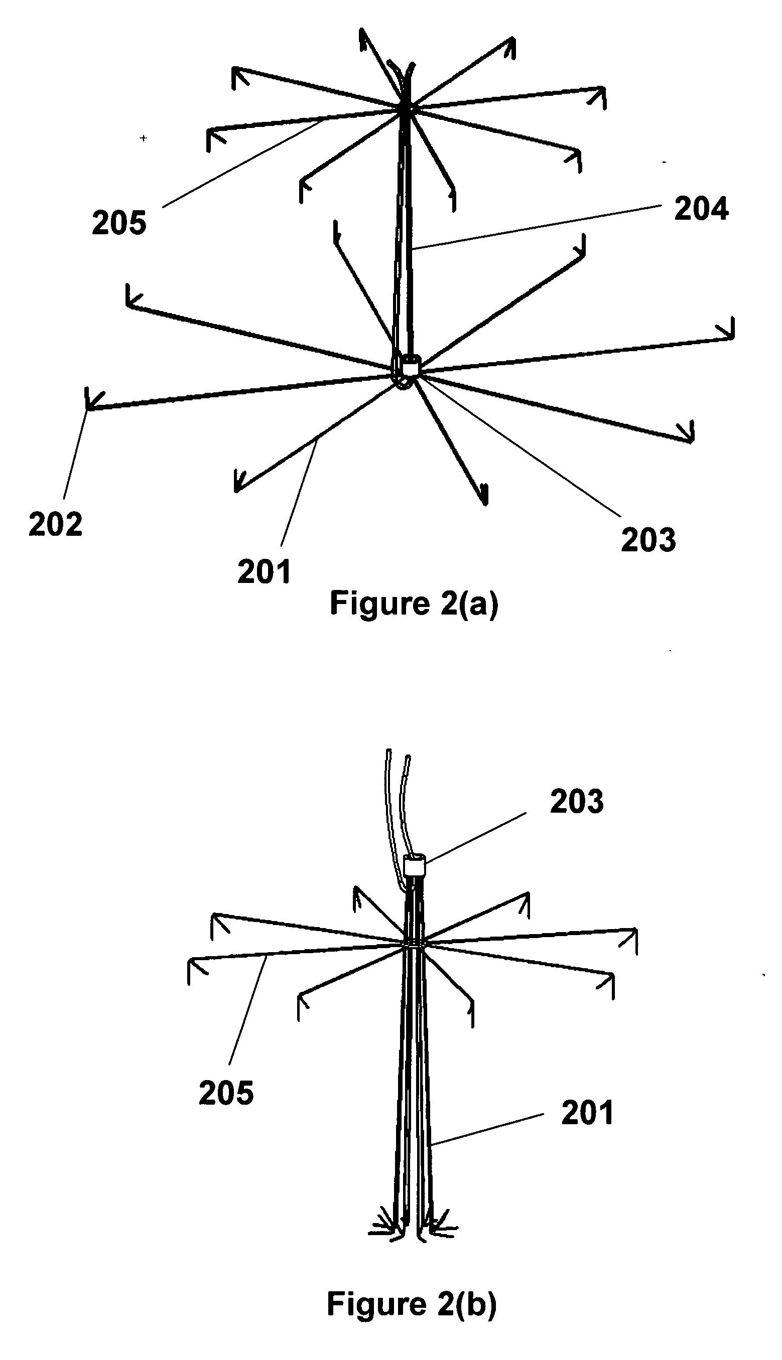
[0045] The present invention can comprise a device to close puncture wounds caused by catheter procedures and especially angiography comprised of an expandable umbrella-like device that in the compressed state resides in a sheath, and after being expelled from the sheath assumes a planar or conical or other shape, engages vessel wall by means of tissue hooks or penetrators, is collapsed, analogous to umbrella tines, and brings the edges of the vessel wound or puncture into apposition. The device can have a retaining locking device that prevents the umbrella-like structure from reopening. This locking can be achieved by mechanical means including deformable enlargements on the members, dentates, male-female connectors, peg and hole, or other directional mating / locking devices on the members and retaining locking device. This locking device can have a washer like appearance, but can also take a number of different forms, including an inverted umbrella device made of metal, plastic, co...


PUM


Abstract

A vascular closure device comprised of a sheath-delivered expandable, umbrella-like device with structural radial members with terminal and non-terminal hooks that engage the vessel wall. Unlike other vascular closure umbrella-type devices that effect closure by opening of the umbrella to cover an opening, the present invention effects closure of the aperture with closure of the umbrella. The closure can be maintained by a retainer lock that slides down the members, causing contraction, bringing the members into a compressed configuration (e.g., a parallel orientation of linear members) and the wound edges together, permitting immediate vascular closure and healing of the blood vessel. The device can be delivered and recovered by an intravascular sheath.

Description

BACKGROUND [0001] The present invention relates to methods and apparatuses for closing punctures and apertures in human and animal tissue and to methods and apparatuses for inserting such an apparatus into such tissue to perform such closure functions. [0002] During angiography and related procedures, catheters are inserted through an incision or puncture in the skin and underlying tissues to access an artery or vein, typically in the groin, neck, or subclavian areas of a patient. The catheter can be inserted through a puncture in the blood vessel and guided to the desired site to perform interventional procedures such as angiography, angioplasty, plaque removal, and infusion of a therapeutic substance. After the procedure is completed and the catheter is removed from the patient, the access hole must be closed to prevent massive hemorrhage. This is conventionally achieved by applying pressure over the blood vessel manually and then by applying a pressure bandage, compressive weight...

Claims


Application Information

Patent Timeline
Patent Type & Authority Applications(United States)
IPC IPC(8): A61M5/178
CPCA61B17/0057A61B17/0643A61B2017/00663A61B17/10A61B2017/0641A61B17/083A61B2017/00668
Inventor SIBBITT, WILMER L. JR.SIBBITT, RANDY R.
Owner ABBOTT CARDIOVASCULAR
Why Eureka
Try Eureka