
Pulsed hydraulic clothes washer

a technology of clothes washer and pulsating pump, which is applied in the direction of washing machine with receptacles, detergent compounding agents, liquid/gas/vapor textile treatment, etc., can solve the problems of frequent complex construction, high energy consumption of typical modern washing machines, and the possibility of mechanical failur

Inactive Publication Date: 2015-10-01
DREWRY KRISTINN G +1
View PDF2 Cites 5 Cited by
  • Summary
  • Abstract
  • Description
  • Claims
  • Application Information

AI Technical Summary

Benefits of technology

This patent describes a new washing machine that creates large bubbles in the water to agitate the wash and rinse stages without causing excessive damage to the clothing. The machine also has a press mechanism to reduce moisture content in the clothing without using centrifugation. The technical effect of this patent is improved washing efficiency with minimal damage to clothing.

Problems solved by technology

Because agitation and centrifugation of heavy, wet clothing require the washing machine motor to supply considerable torque, the energy consumption of typical modern washing machines are relatively high.
Further, because a typical modern washing machine relies on substantial interacting parts in the control and transmission of mechanical energy from the electric motor to agitate and dry clothing, construction is frequently complex and eventual mechanical failure is certain.
Further, because agitation of clothing is accomplished by the movement of rigid mechanical components against clothing (agitators or impellers in the case of top loaders, paddles in the case of front loaders), delicate clothing can be damaged by the shear forces presented thereby.
Further, because considerable unbalanced centripetal forces may be generated during centrifugation, modern washing machines are noisy during the drying stage of the wash cycle and often require complex mechanical arrangements to avoid unwanted movement of the machine in place.

Method used


Image

  • Pulsed hydraulic clothes washer
  • Pulsed hydraulic clothes washer
  • Pulsed hydraulic clothes washer

Examples


Embodiment Construction

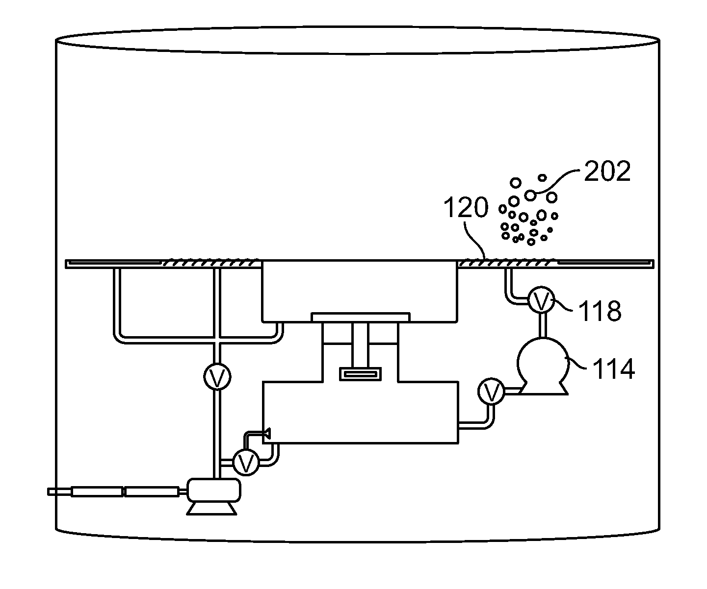
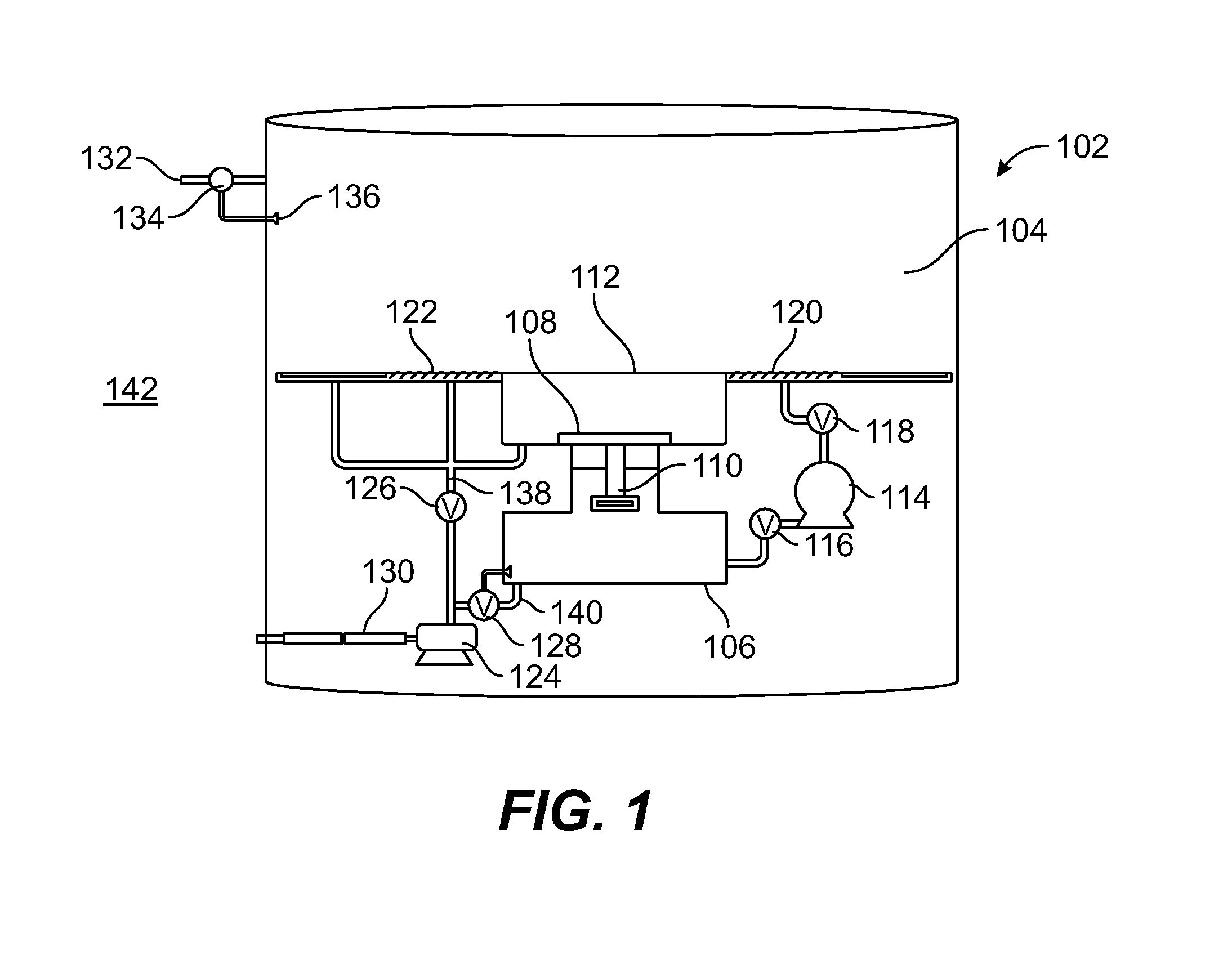
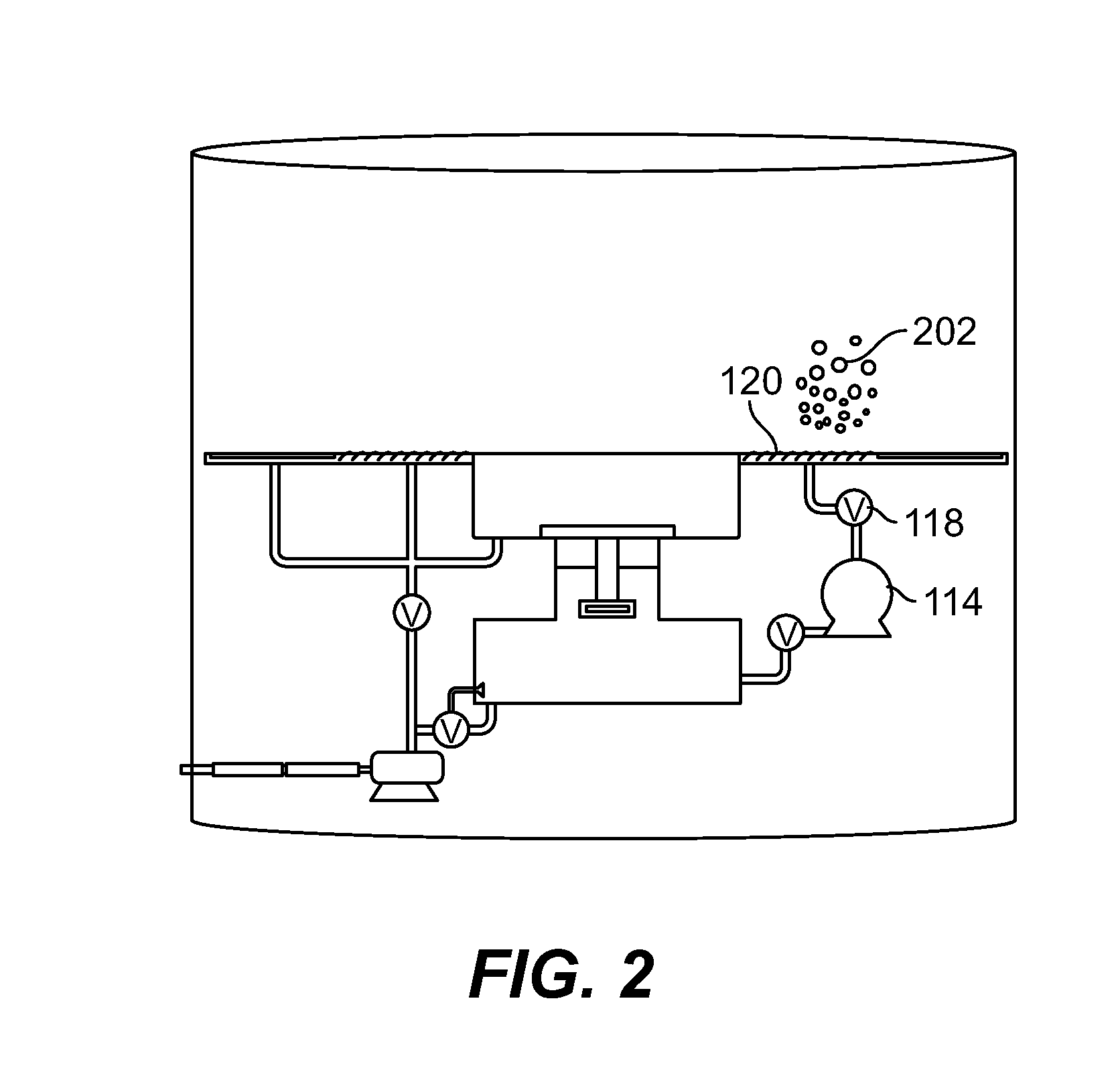
[0025]FIG. 1 depicts an embodiment of the clothes washer 102, wherein a washing chamber 104 may be filled from a water source 132 when valve 134 is opened. In the depicted embodiment, washer 102 will fill with water to a predetermined level controlled by electronic water level sensor 136, which signals valve 134 to close when water has reached the predetermined level for clothes washer operation. As will be appreciated by those of skill in the art, a number of other means may be employed for filling the washing chamber with water to a predetermined level. Such means include a float valve such as commonly used in flush toilets. Alternatively, such means may comprise a timed solenoid valve, which simply opens for a fixed period of time and then closes. Yet further, such means for filling with water may comprise a valve that is manually operated based on information displayed on a fill gauge. Those of skill in the art will realize that the present invention contemplates any and all suc...


PUM


Abstract

A new washing machine apparatus comprises a washing compartment having a means by which large mixing bubbles six inches or more in diameter may be generated to rise from the lower portion to the upper portion of the compartment. As they rise through the compartment, these large mixing bubbles generate substantial convection currents in clothing suspended in washing solution or rinse water in the compartment, thereby providing the agitation needed for wash and rinse stages of the wash cycle with minimal shear force. Embodiments further comprise a press mechanism for the dry cycle, substantially reducing the moisture content of washed clothing without use of centrifugation.

Description

BACKGROUND OF THE INVENTION[0001]1. Field of the Invention[0002]This invention relates to an apparatus for washing articles of clothing. More specifically, this invention relates to an apparatus that washes clothes by propagating large mixing bubbles through a slurry of water, clothing and chemical cleaning agent, thereby producing convection currents that agitate the slurry.[0003]2. Description of the Related Art[0004]Automatic clothes washing machines have long been a fixture of modern living in the industrial age. While modern washing machines may be based on a wide range of designs and approaches to washing clothing, the related art shares common characteristics. Automated washing of clothing with water is accomplished by a wash cycle performed on clothing placed in the washing machine. A wash cycle may be preceded by pre-soaking or other treatment of clothing in the washing machine prior to the actual wash cycle. Such treatment typically exposes soiled clothing to water and / or ...

Claims


Application Information

Patent Timeline
IPC IPC(8): D06F35/00D06F17/12D06F34/14
CPCD06F17/12D06F35/002D06F34/14
Inventor DREWRY, KRISTINN G.KOOPMANS, RICHARD J.
Owner DREWRY KRISTINN G
Learn More