Vehicle head-up display device

a display device and head-up technology, applied in the direction of instruments, cathode-ray tube indicators, polarising elements, etc., can solve the problems of deteriorating the mountability of the vehicl

Active Publication Date: 2016-06-23
DENSO CORP
View PDF3 Cites 69 Cited by
  • Summary
  • Abstract
  • Description
  • Claims
  • Application Information

AI Technical Summary

Benefits of technology

[0014]Accordingly, by setting the angle α, it is possible to avoid a situation, without any increase in the body size, where one of a sum of the luminance of an s-polarized light and a p-polarized light when a driver views the virtual image with his naked eyes, and the luminance of the p-polarized light when viewing the virtual image through polarized sunglasses is extremely lowered.

Problems solved by technology

As described above, in PTL 1, because the retardation plate is provided separately, a body size of the device tends to be large, resulting in a deteriorated mountability of the vehicle.

Method used


Image

  • Vehicle head-up display device
  • Vehicle head-up display device
  • Vehicle head-up display device

Examples


first embodiment

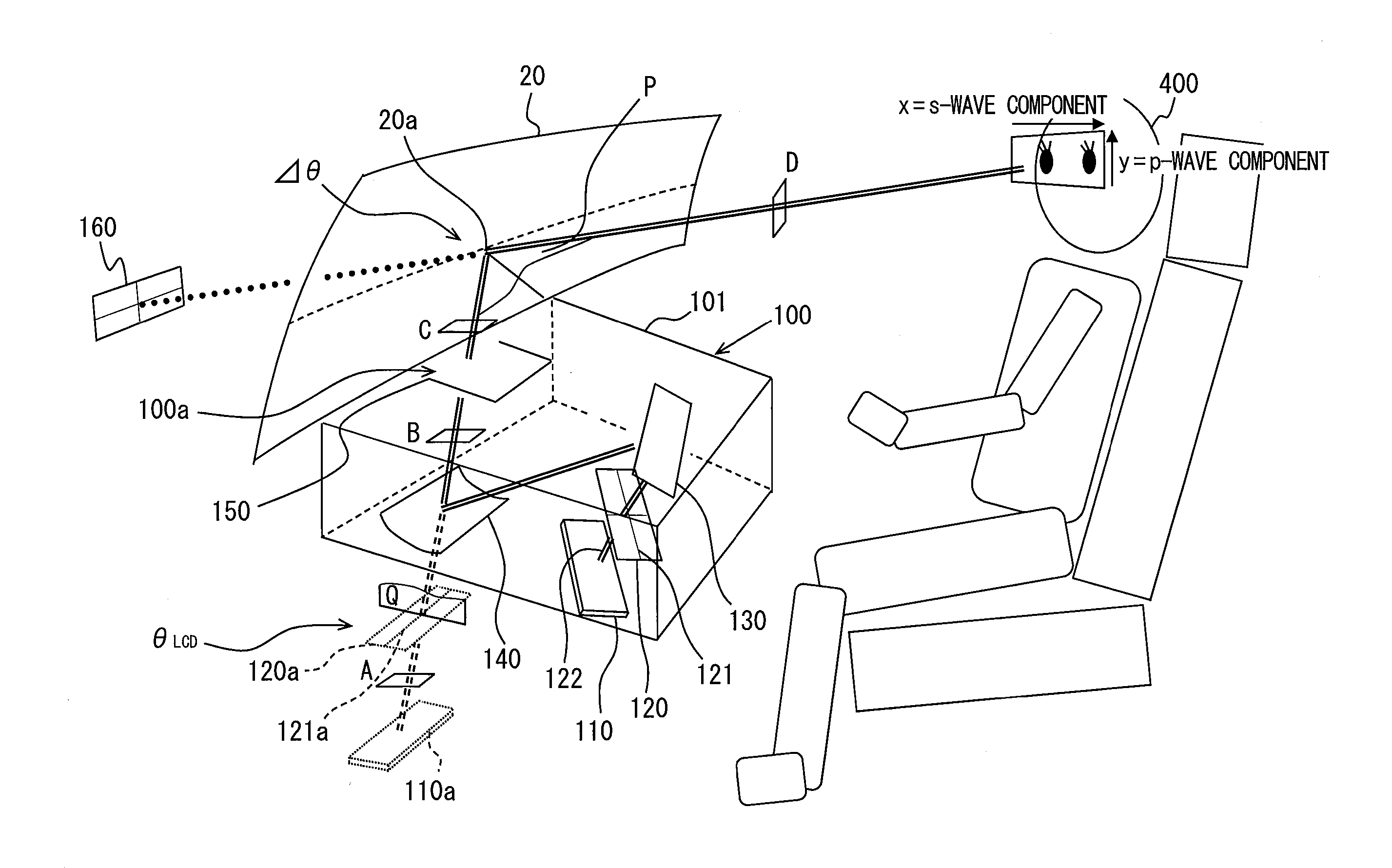
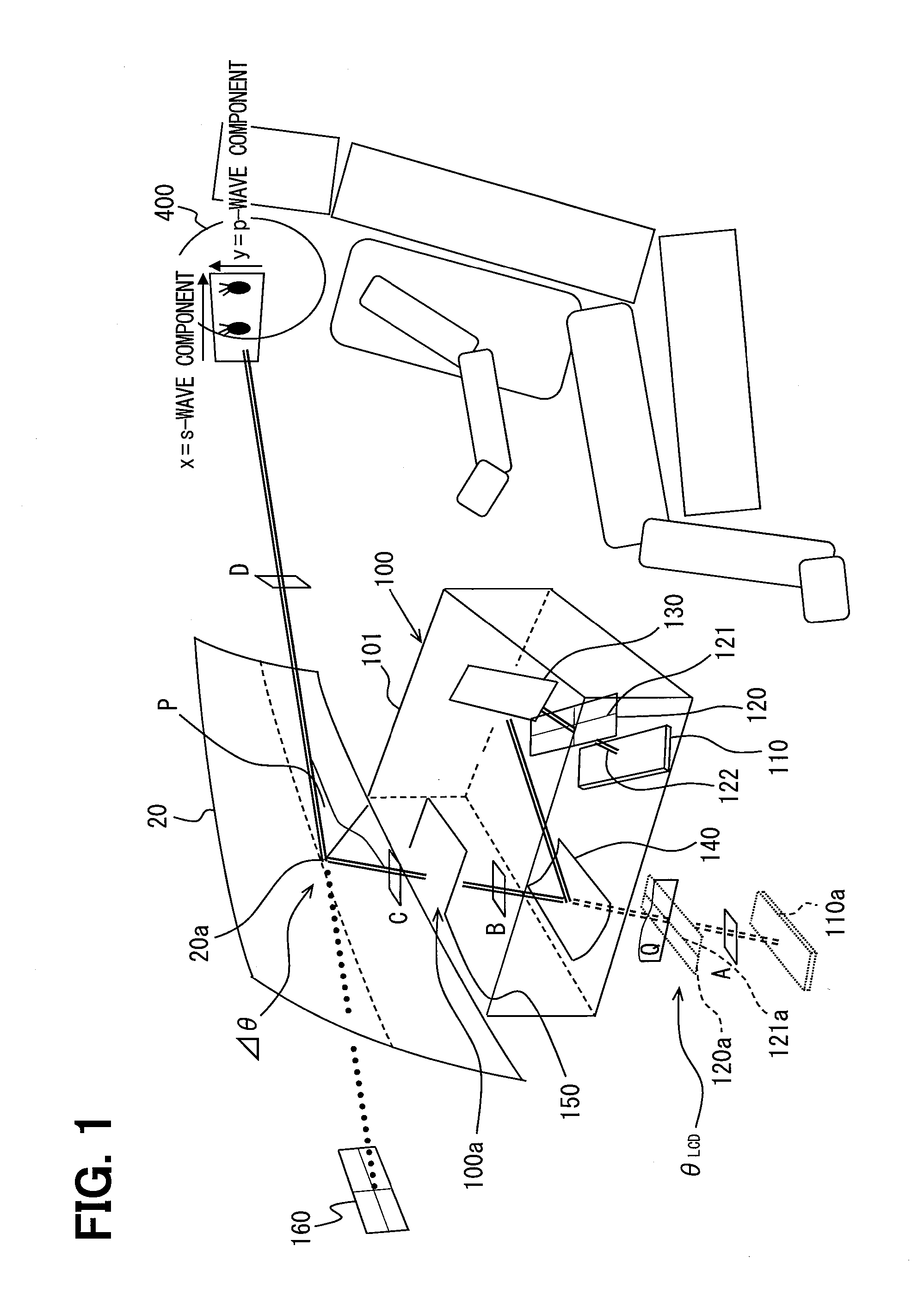
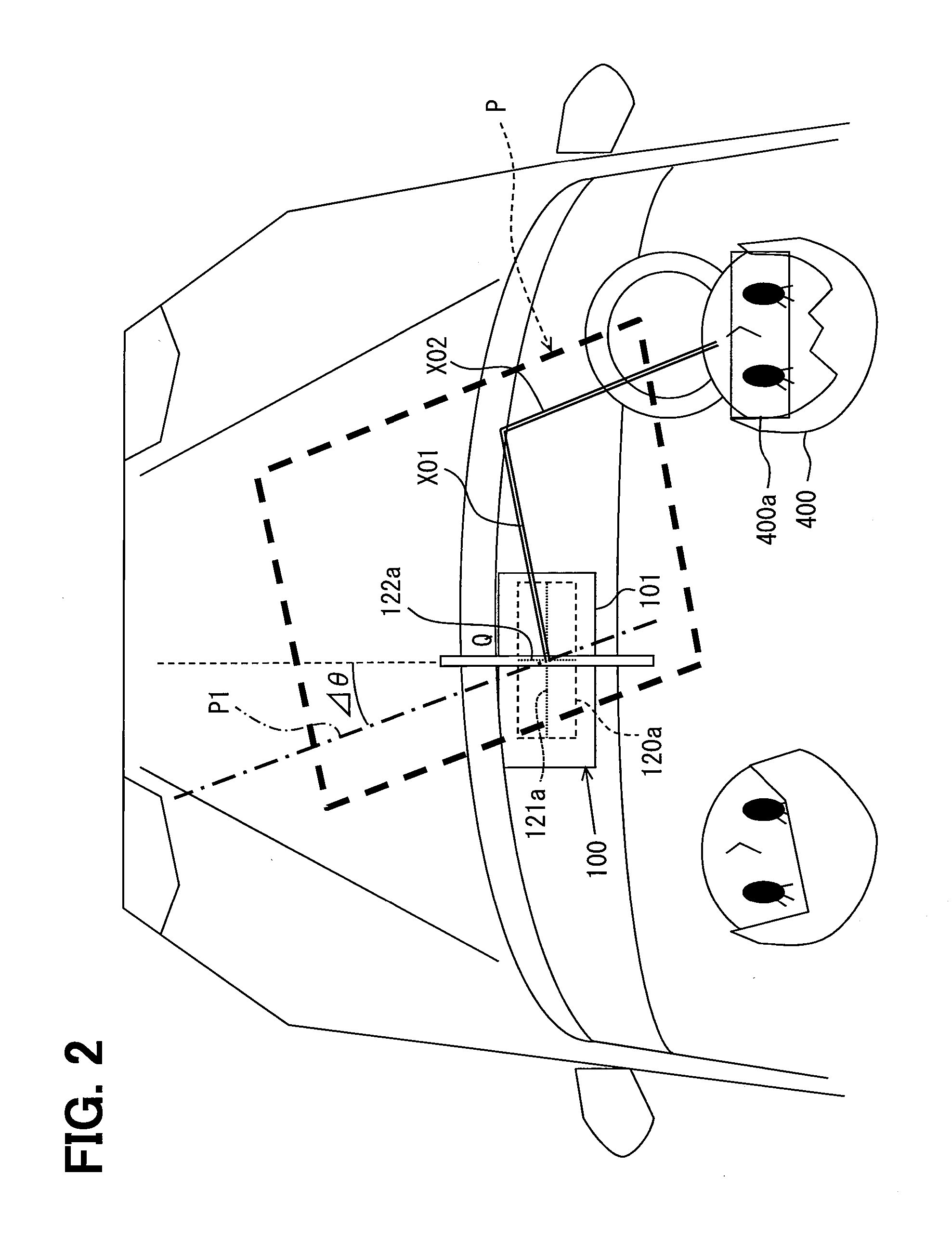
[0030]A vehicle head-up display device 100 according to a first embodiment will be described with reference to FIGS. 1 to 9. As illustrated in FIG. 1, a vehicle head-up display device 100 has a display 120 housed in a casing 101. A display light indicating display information is emitted from the display 120. The emitted display light is projected onto a projection position 20a of a windshield 20 for a vehicle. The vehicle head-up display device 100 generates a display image 160 of display information on a vehicle front extension line of a line between an eye box 400a and a projection position 20a. With the above configuration, the display image 160 is visually recognized as a virtual image by a driver 400. In this example, the eye box 400a is set in a predetermined area set in a vehicle interior in advance. Specifically, the eye box 400a is set as an area where eyes of the driver 400 are positioned during driving. The driver 400 can visually recognize the display image 160 and a for...

second embodiment

[0104]A method of selecting a cover mounting angle α according to a second embodiment will be described below. In the second embodiment, the cover mounting angle α is selected so that a luminance I of (S+P)-polarized light in a display image 160 has a maximum value. FIG. 9 shows a polarization direction of a display light according to the second embodiment.

[0105]In the second embodiment, the cover mounting angle α is selected so that the polarization direction of the display light at a position D is in parallel to an x-axis (a longitudinal axis of a virtual image of a display which is reflected on a reflector). In other words, the cover mounting angle α is selected so that an s-polarized light component becomes largest. As described above, a reflectance Rs of the s-polarized light is larger than a reflectance Rp of a p-polarized light. For that reason, the luminance I of the virtual image by the naked eyes becomes maximum.

[0106]FIG. 10 illustrates an example of the cover mounting an...

third embodiment

[0115]In a third embodiment, as illustrated in FIG. 11, a motor 300 is further disposed in a casing. The motor 300 is connected to a dust-proof cover 150. The motor 300 is connected to a cover operation remote controller 310.

[0116]With the above configuration, the dust-proof cover 150 rotates according to the rotation of the motor 300. Because an angle between a rolling direction of the dust-proof cover 150 and a virtual image longitudinal axis 121a changes, a cover mounting angle α changes. Therefore, a driver 400 can increase or decrease a luminance I of a display image 160 and a luminance Ip of a p-polarized light component of the display image 160 according to his own preference.

[0117]The operation remote controller 310 is equipped with an up-switch 311 and a down-switch 312. When the up-switch 311 is depressed, the motor 300 rotates so that the dust-proof cover 150 rotates clockwise.

[0118]On the other hand, when the down-switch 312 is depressed, the motor 300 rotates so that th...


PUM


Abstract

In a vehicle head-up display device that reflects a display light transmitted through a dust-proof cover on a windshield or a combiner, and viewably displays display information as a virtual image from a driver's seat of a vehicle, the dust-proof cover has a light transmissive property produced by being rolled, when a line between a first point a first end side of the display in a longitudinal direction of the display and a second point being at the same height as the first point in a second end side opposite to the first end side is a longitudinal axis, and a luminance of a virtual image is adjusted by adjusting an angle between a rolling direction of a resin sheet used for the dust-proof cover and a virtual image longitudinal axis, which corresponds to the longitudinal axis, of a virtual image of the display reflected by the reflector. As a result, a polarization state of the display light is changed to enable the luminance of the virtual image to be adjusted without any increase in the number of parts and a body size.

Description

CROSS-REFERENCE TO RELATED APPLICATION[0001]The present application is based on Japanese Patent Application No. 2013-163503 filed on Aug. 6, 2013 the contents of which are incorporated herein by reference.TECHNICAL FIELD[0002]The present disclosure relates to a vehicle head-up display device that reflects an image displayed on a display toward a windshield or a combiner of a vehicle, and viewably displays a virtual image of the image from an eye point in a vehicle interior.BACKGROUND ART[0003]A conventional vehicle head-up display device disclosed in, for example, PTL 1 has been known. The vehicle head-up display device in PTL 1 includes a liquid crystal display panel and a light emitting element that illuminates the liquid crystal display panel. The vehicle head-up display device projects a display light including a linearly polarized light onto a windshield to display the virtual image.[0004]The vehicle head-up display device of PTL 1 rotates a polarization axis of the display lig...

Claims


Application Information

Patent Timeline
Patent Type & Authority Applications(United States)
IPC IPC(8): G02B27/01G02B27/00B60K35/00
CPCG02B27/0101B60K35/00G02B2027/0154G02B27/0149G02B2027/0118G02B27/0006G02B5/30
Inventor ISHIKAWA, TOSHIKI
Owner DENSO CORP
Why Eureka
Try Eureka