Hold type image display system

Inactive Publication Date: 2008-10-02
GOLD CHARM LTD
View PDF6 Cites 54 Cited by
  • Summary
  • Abstract
  • Description
  • Claims
  • Application Information

AI Technical Summary

Benefits of technology

[0017]As an exemplary advantage according to the invention, the present invention can finely adjust the black image insertion rate with respect to one frame period while taking into consideration the balance between the merit of reducing the moving image blur and the demerit of lowering in lumi

Problems solved by technology

However, in the hold type display device such as LCD, an image is continued through a frame period as opposed to an impulse type display device such as CRT display, and thus a moving image tends to become unclear.
However, in most liquid crystal display devices pseudo-driven in the impulse type display, a black signal and a video signal are alternately written to each pixel at a constant cycle, and thus only the black signal is written in one polarity and only the video signal is written in the other polarity if the cycle of inversion drive and the cycle of black insertion coincide, whereby the DC component is applied to the liquid cr

Method used


Image

  • Hold type image display system
  • Hold type image display system
  • Hold type image display system

Examples


Example

First Exemplary Embodiment

[0053]An example in which at least two gate drivers capable of collectively enabling the gate output with respect to a plurality of gate lines of a display panel are arranged will be described as a first exemplary embodiment of the present invention.

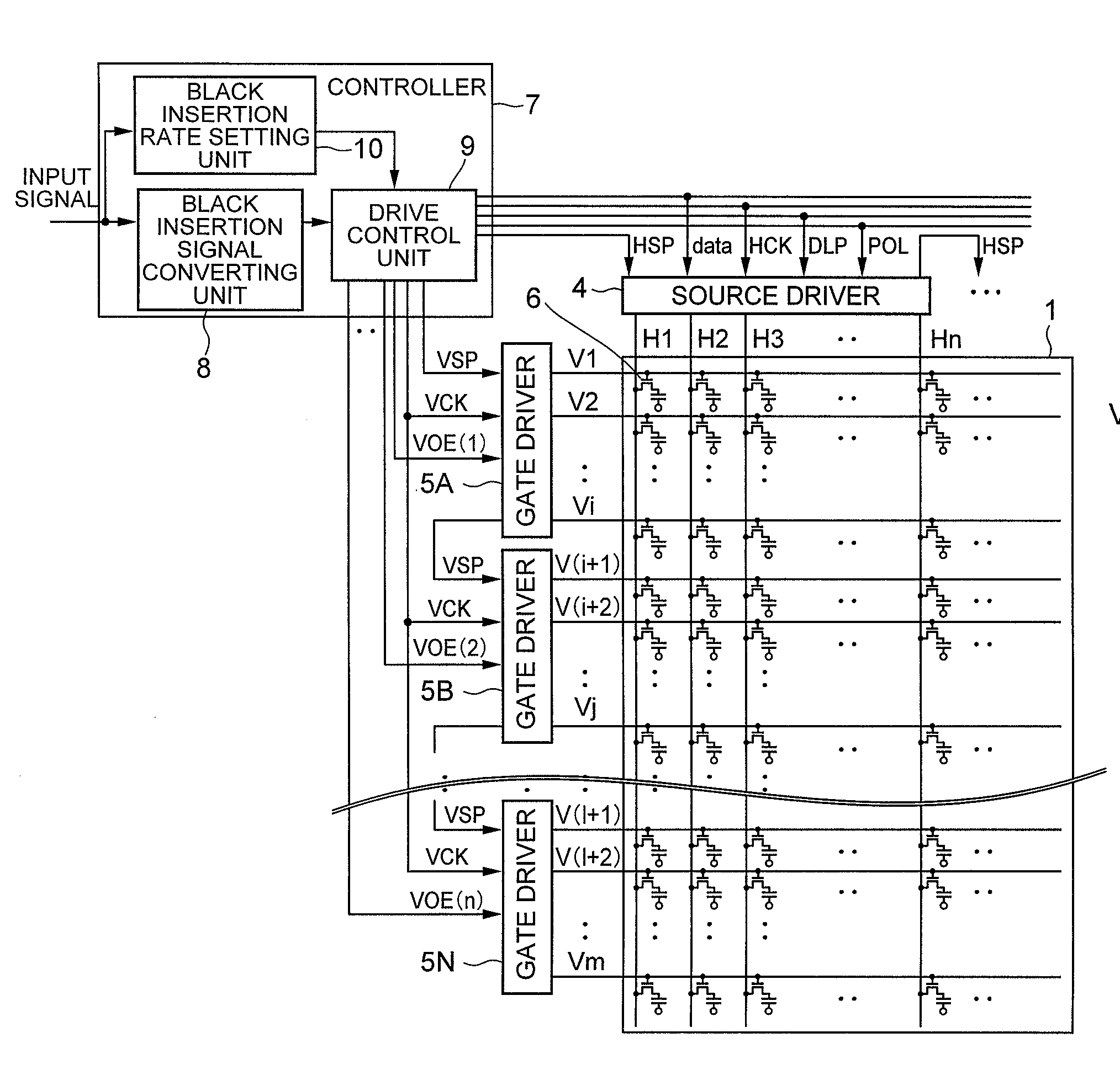
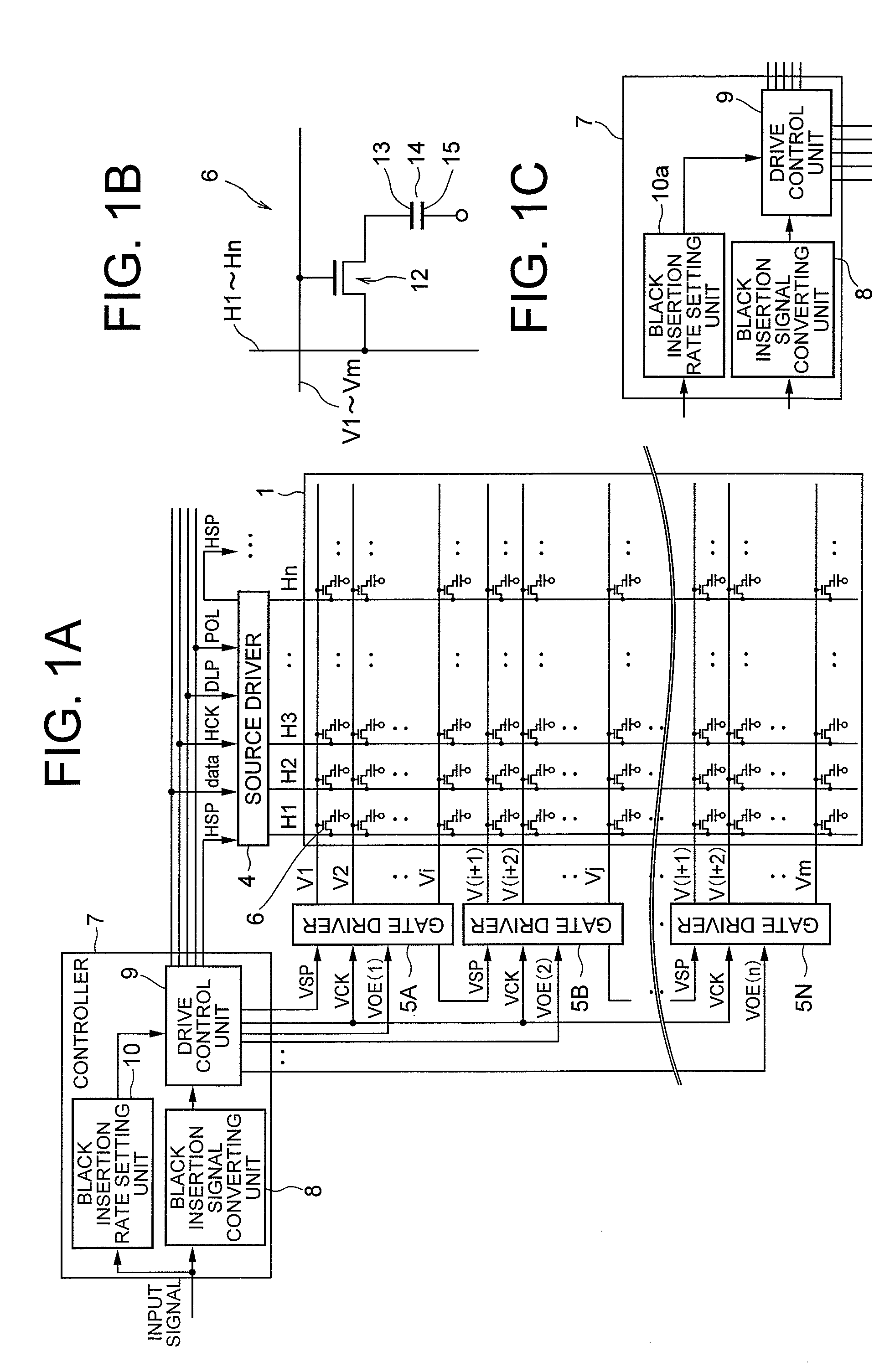
[0054]As shown in FIG. 1A, a display panel 1 of the image display device of the first exemplary embodiment of the present invention has a configuration in which m (m is a natural number) gate lines V1 to Vm and n (n is a natural number) source lines H1 to Hn are arrayed so as to intersect each other to a matrix form, and a pixel 6 is formed at each intersection of the gate lines and the source lines. A source driver 4 is connected to the source lines H1 to Hn, the gate lines V1 to Vn are divided into a plurality of gate line groups, and gate drivers 5A to 5N are connected to the gate lines of each gate line group.

[0055]In the example of FIG. 1A, the gate driver 5A is connected to the gate lines V1 to Vi of the g...

Example

Second Exemplary Embodiment

[0110]Next, a second exemplary embodiment of the present invention will be described.

[0111]FIG. 12 is a view showing a configuration of an image display device of a second exemplary embodiment according to the present invention. Same reference numerals are denoted for components same as in the first exemplary embodiment shown in FIG. 1A. As shown in FIG. 12, the second exemplary embodiment has a backlight 21 arranged at the rear surface of the display panel 1 when seen from the user, in addition to the configuration similar to the first exemplary embodiment. A black insertion rate setting unit 20 has a function of temporarily storing information for one frame of the input video signal sequentially input for every frame, and comparing the video signal of one frame of the input video signal and the video signal of the previous frame that is temporarily stored to determine the black image insertion rate and the light control luminance of the backlight based o...


PUM


Abstract

The present invention aims to prevent display luminance difference and burning with a line at which the polarity inversion switches when the order of inversion of black and video changes in the middle of the screen by a frame polarity inversion drive in a liquid crystal display device for performing black insertion drive. An enable signal (VOE) to each gate driver 5A to 5N is independently controlled, a start pulse (VSP) input to write a black signal is performed at an arbitrary timing within one frame period with respect to the gate driver 5A to insert a black image within one frame period, a write polarity of the video signal is inverted in frame cycle with the video display start pulse as a base point, and a write polarity of the black image signal is inverted in frame cycle with the black display start pulse as a base point.

Description

CROSS-REFERENCE TO RELATED APPLICATIONS[0001]This application is based upon and claims the benefit of priority from Japanese patent application No. 2007-086191, filed on Mar. 29, 2007, and Japanese patent application No. 2008-039352, filed on Feb. 20, 2008, the disclosure of which is incorporated herein in its entirety by reference.BACKGROUND OF THE INVENTION[0002]1. Field of the Invention[0003]The present invention relates to image display devices and image display methods thereof, and image display programs, in particular, to a hold type image display system.[0004]2. Description of the Related Art[0005]A liquid crystal display (LCD) is being widely used since it is thin and does not occupy as much installation area compared to a CRT (Cathode Ray Tube) display. However, in the hold type display device such as LCD, an image is continued through a frame period as opposed to an impulse type display device such as CRT display, and thus a moving image tends to become unclear.[0006]In th...

Claims


Application Information

Patent Timeline
IPC IPC(8): G09G5/00G09G3/36
CPCG09G3/3614G09G2310/061G09G2320/0257G09G2320/0261G09G2320/046G09G3/3666G09G2320/106G09G3/36G09G3/342G09G2310/024H04N5/66G09G2320/062
Inventor KIMURA, HIROAKI
Owner GOLD CHARM LTD
Why Eureka
Try Eureka