
Smart Device Programmable Electronic Luggage Tag and Bag Mountings Therefore

a smart device and luggage tag technology, applied in the field of electronic luggage tags, can solve the problems of not being able to meet the needs or desires of the airline industry, inadequate tags,

Active Publication Date: 2016-06-30
VIEWTAG
View PDF2 Cites 21 Cited by
  • Summary
  • Abstract
  • Description
  • Claims
  • Application Information

AI Technical Summary

Benefits of technology

The invention is a small electronic tag that can change its displayed image based on external signals received through a radio. It is powered by a battery and has a manual input device for programming the image. This allows the user to easily customize the tag with their own images or messages.

Problems solved by technology

However, these forms of tags have, for various reasons, not been found adequate to meet the needs or desires of the airline industry.

Method used


Image

  • Smart Device Programmable Electronic Luggage Tag and Bag Mountings Therefore
  • Smart Device Programmable Electronic Luggage Tag and Bag Mountings Therefore
  • Smart Device Programmable Electronic Luggage Tag and Bag Mountings Therefore

Examples


Embodiment Construction

[0021]Certain terminology is used in the following description for convenience only and is not limiting. The words “right,”“left,”“lower” and “upper” designate directions with respect to components in the drawings to which reference is made. The words “inwardly” and “outwardly” refer to directions toward and away from, respectively, the geometric center of the stated component and designated parts thereof. The terminology includes the words above specifically mentioned, derivatives thereof and words of similar import.

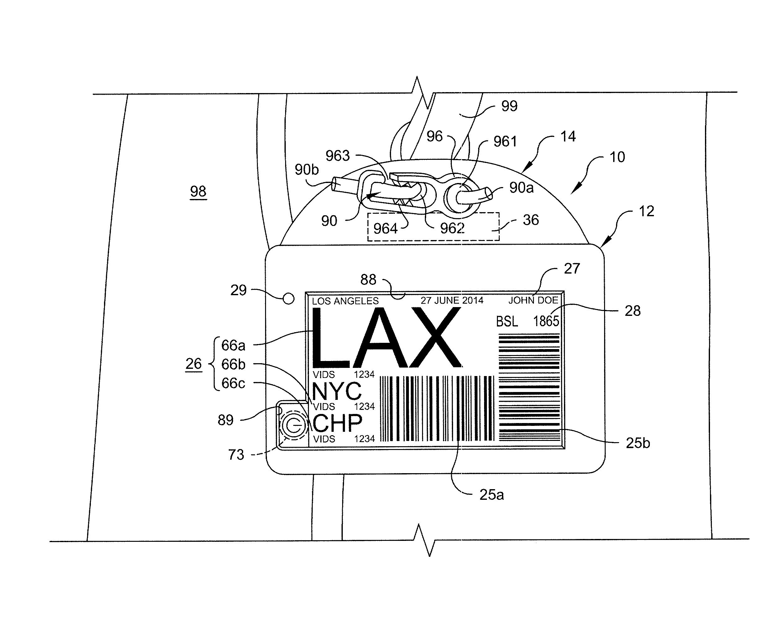
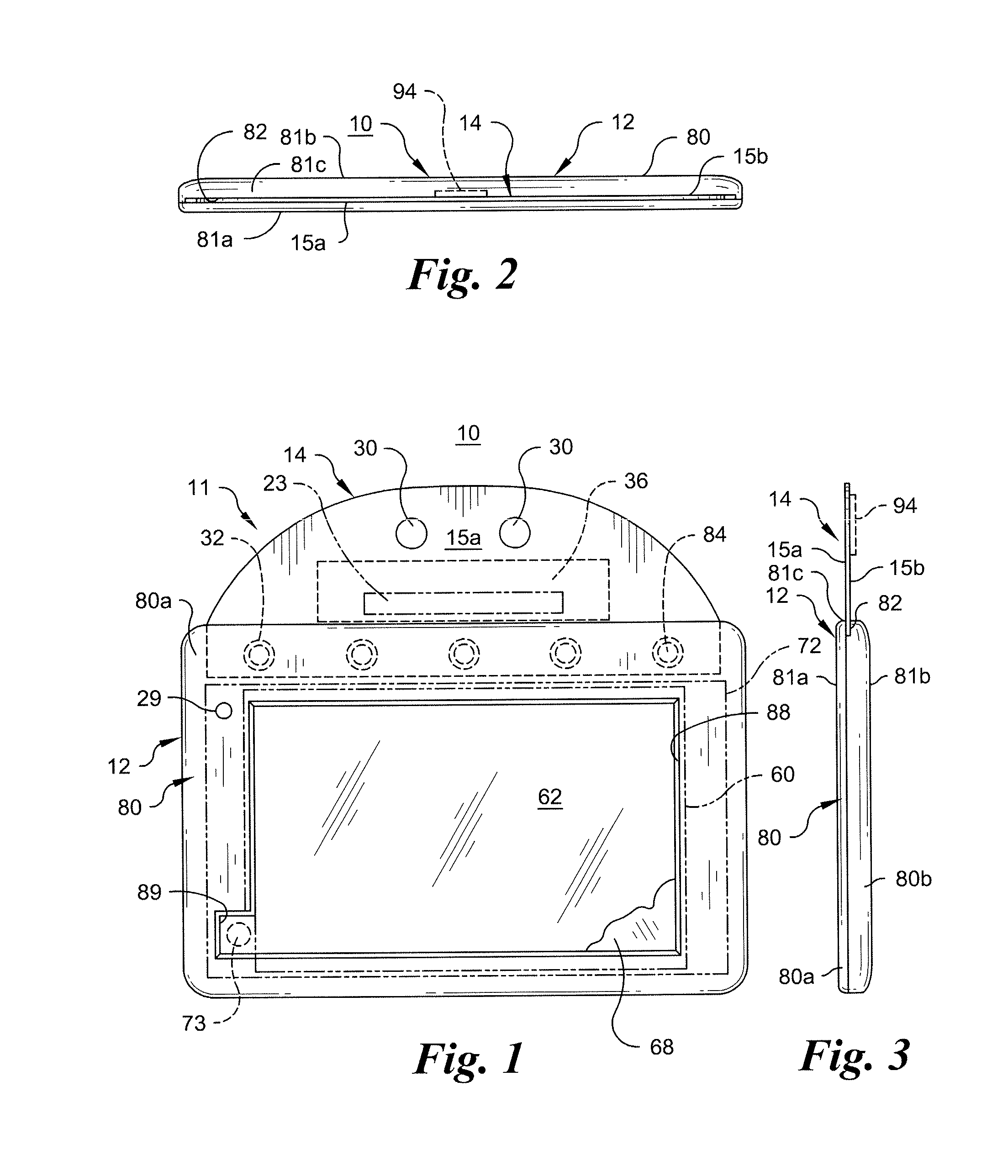
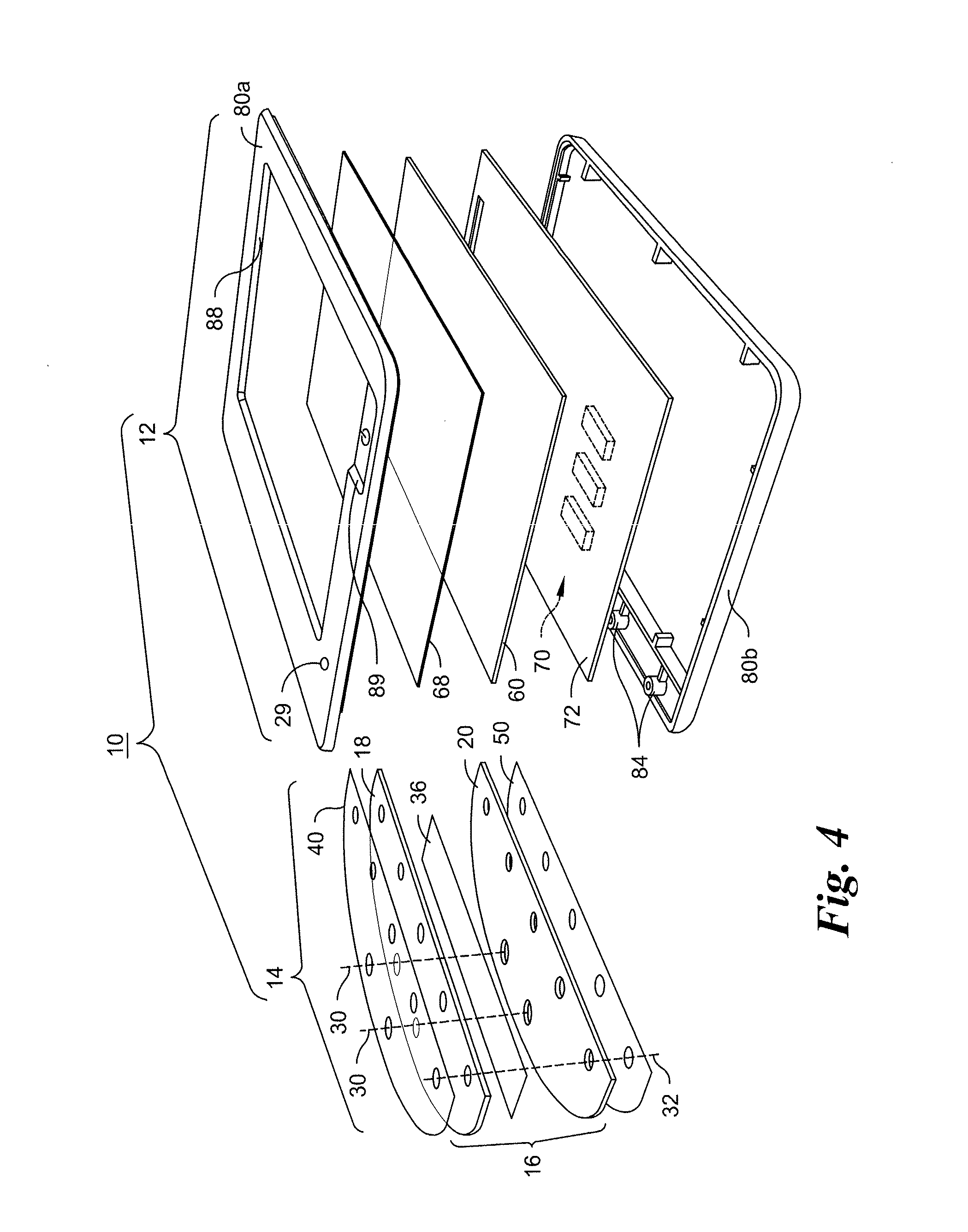
[0022]FIGS. 1-4 depict a first exemplary embodiment, smart device programmable luggage tag with RFID transponder assembly and wirelessly reprogrammable electronic visual display according to the present invention and indicated generally at 10. Tag 10 and other tags to be described are “programmable” or “reprogrammable” in the sense that the image presented by visual display can be changed through the provision of appropriate data to control drivers of the display. Tag 1...


PUM


Abstract

Luggage tag has a body with one bistable electronic visual display assembly and one screen, a radio receiver and a processor configured to convert short range command signals detected by the receiver into signals suitable to modify the image on the display screen. A manually operated switch activates the receiver and processor with a battery for a short time period sufficient to receive the command signals and modify the display. The electric components are encapsulated with an RFID transponder assembly in one resiliently flexible, plastic laminate body or the transponder assembly is encapsulated in a planar, plastic laminate flap permanently attached to a separate rigid protective case housing the remaining electric components. The tag is secured to a bag with a flexible connector, under tension, to retain the tag in a fixed position always exposing the sole display screen.

Description

CROSS-REFERENCE TO RELATED APPLICATIONS[0001]This application is a Continuation-in-part of U.S. patent application Ser. No. 14 / 516,204 filed Oct. 16, 2014, which is a Continuation-in-part of U.S. patent application Ser. No. 14 / 207,836 filed Mar. 13, 2014 and now abandoned, which is a Continuation of Ser. No. 13 / 290,559 filed Nov. 7, 2011 and now abandoned, which is a Continuation-in-part of Ser. No. 12 / 960,941 filed Dec. 6, 2010 and now U.S. Pat. No. 8,052,061, which is a Continuation-in-part of Ser. No. 12 / 416,637 filed Apr. 1, 2009 and now U.S. Pat. No. 7,845,569. It is related to U.S. Patent Application Nos. 61 / 891,666 filed Oct. 16, 2013, 61 / 920,574 filed Dec. 24, 2013, 61 / 942,917 filed Feb. 21, 2014, 61 / 970,137 filed Mar. 25, 2014, 62 / 016,874 filed Jun. 25, 2014, 62 / 034,563 filed Aug. 7, 2014, 62 / 049,032 filed Sep. 11, 2014, 62 / 086,483 filed Dec. 2, 2015 and Ser. No. 29 / 497,596 filed Jul. 25, 2014. All of the above-identified applications are incorporated by reference herein in...

Claims


Application Information

Patent Timeline
Patent Type & Authority Applications(United States)
IPC IPC(8): A45C13/42G06F3/14G06K19/077G08C17/02
CPCA45C13/42G06K19/07749G06F3/14G08C17/02G06K19/04G06K19/06028G06K19/06187G06K19/07707G06K19/07726G06K19/12G06K19/14
Inventor WARTHER, RICHARD O.
Owner VIEWTAG
Learn More