Magnification in Ophthalmic Procedures and Associated Devices, Systems, and Methods

a technology for ophthalmology and ophthalmology, applied in the field of magnification in ophthalmological surgical systems, can solve the problems of compromising visualization by surgeons, affecting the operation, and unable to resolve some fine details, and achieves the effects of large field of view, high magnification, and large field of view

Active Publication Date: 2016-06-30
ALCON INC
View PDF2 Cites 53 Cited by
  • Summary
  • Abstract
  • Description
  • Claims
  • Application Information

AI Technical Summary

Benefits of technology

[0008]The presented solution fills an unmet medical need with a unique solution to provide simultaneous high magnification and a large field of view while viewing a surgical procedure using a surgical microscope. An imaging device, such as a camera, can track the surgeon's area of interest, such as a tip of a surgical tool, in real time. The surgeon's area of interest can be magnified and overlaid onto a portion of the original field of view of the surgical microscope. The surgeon can view the magnified image as well as the original field of view. Thus, a large field of view and high magnification can be simultaneously obtained.

Problems solved by technology

With the former approach, the surgeon compromises visualization by not being able to resolve some fine details.
With the latter approach, the surgeon needs to frequently adjust the microscope zoom, such as by physically pressing a foot pedal, while holding the surgical tool held steady within a patient's eye, which further complicates the procedure and can increase risk to the patient.

Method used


Image

  • Magnification in Ophthalmic Procedures and Associated Devices, Systems, and Methods
  • Magnification in Ophthalmic Procedures and Associated Devices, Systems, and Methods
  • Magnification in Ophthalmic Procedures and Associated Devices, Systems, and Methods

Examples


Embodiment Construction

[0021]In the following description specific details are set forth describing certain embodiments. It will be apparent, however, to one skilled in the art that the disclosed embodiments may be practiced without some or all of these specific details. The specific embodiments presented are meant to be illustrative, but not limiting. One skilled in the art will realize other material that, although not specifically described herein, is within the scope and spirit of this disclosure.

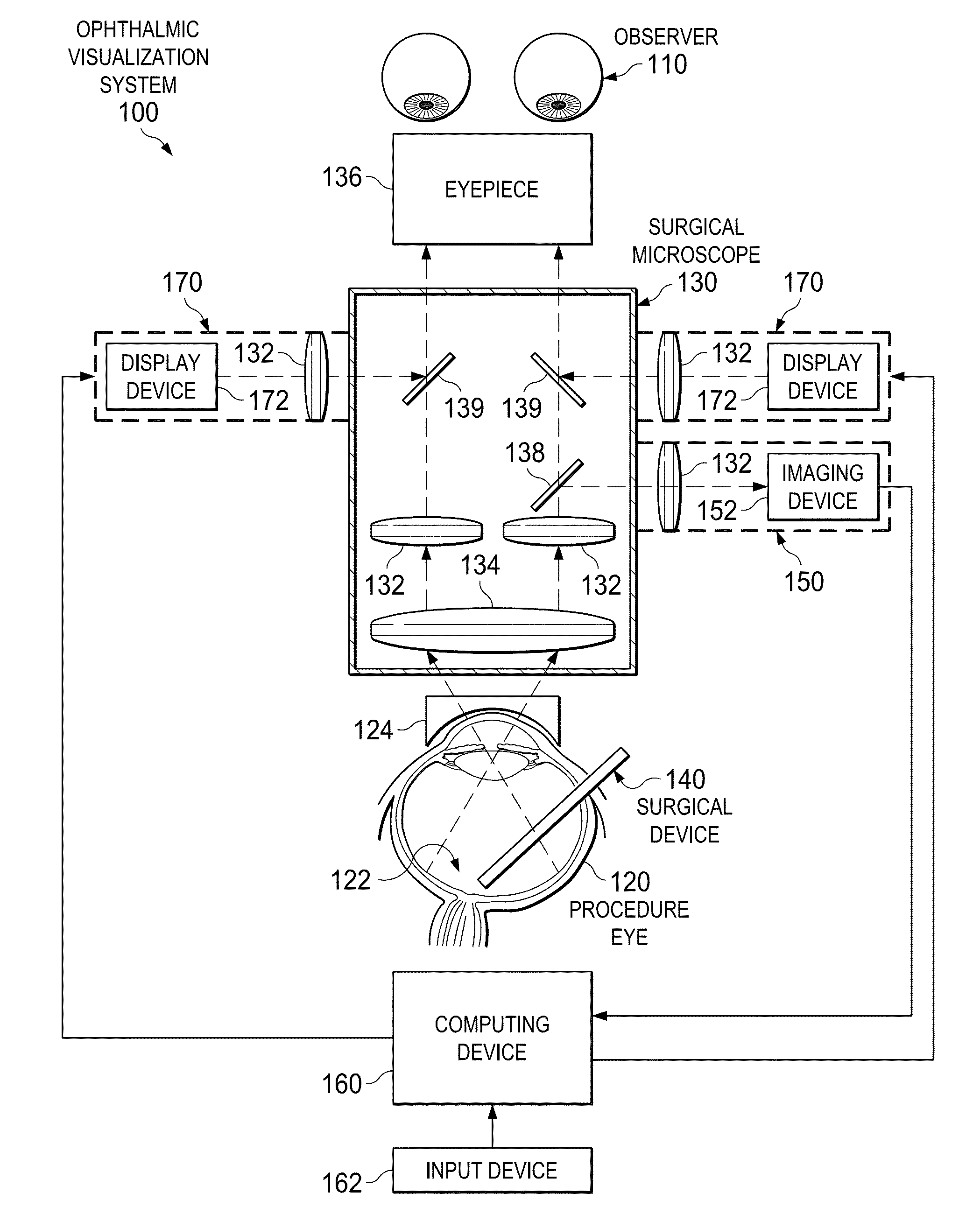
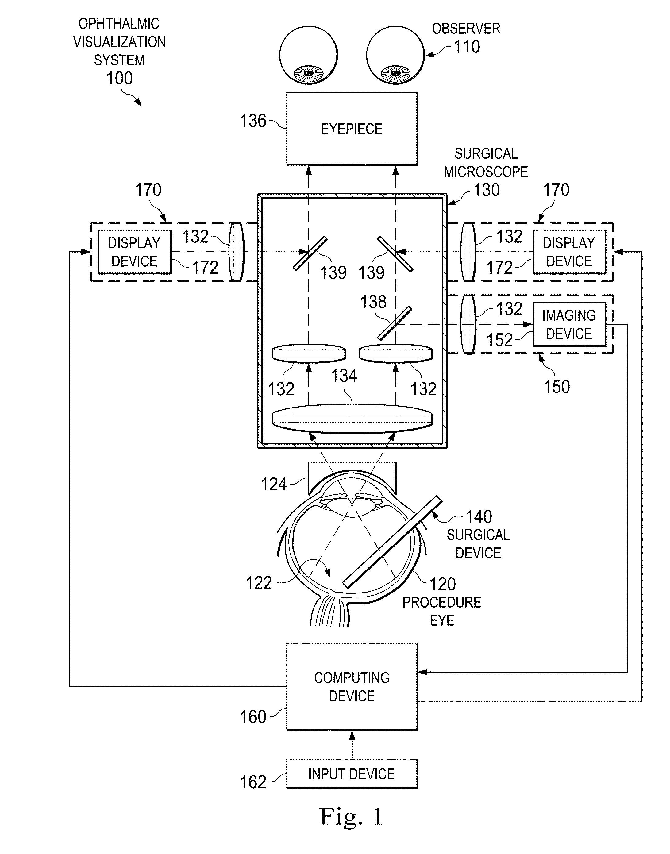
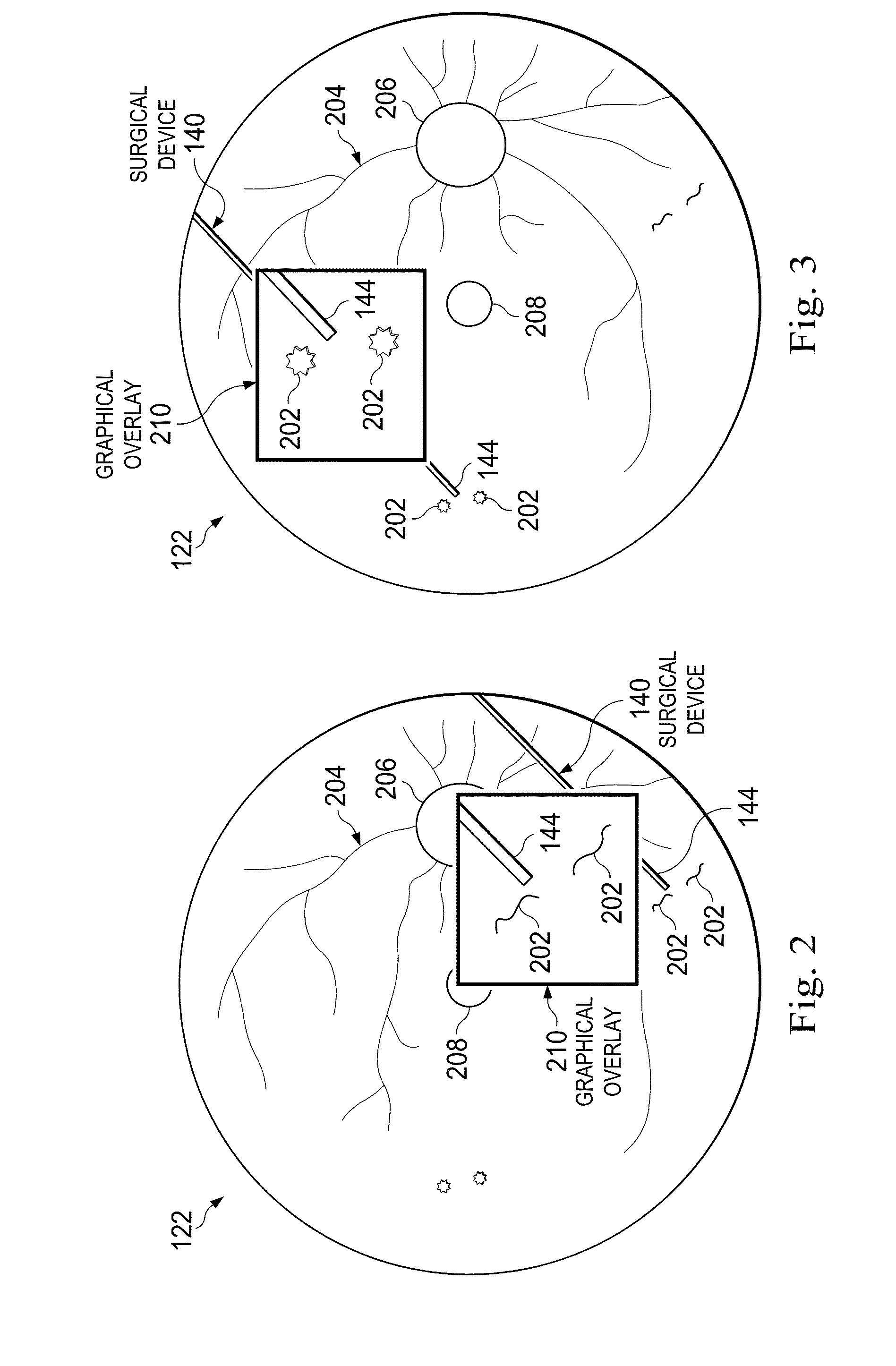
[0022]The present disclosure describes devices, systems, and methods for simultaneously visualizing a large field of view and providing high magnification in an area of interest while a surgeon views a surgical procedure using a surgical microscope. An imaging device can acquire live, real time images of a surgical field that can include target biological tissue and a surgical device operating on the target biological tissue. A computing device can identify and track the surgeon's area of interest in the surg...


PUM


Abstract

An ophthalmic visualization system can include an imaging device configured to acquire images of a surgical field; a computing device configured to determine an area of interest based on the images; and a display device in communication with the computing device and a surgical microscope, wherein the display device is configured to provide a graphical overlay onto at least a portion of a field of view of the surgical microscope, and wherein the graphical overlay includes a magnified image of the area of interest. A method of visualizing an ophthalmic procedure can include receiving images of a surgical field acquired by an imaging device; identifying an area of interest; generating a graphical overlay including a magnified image of the area of the interest; and outputting the graphical overlay to a display device such that the graphical overlay is positioned over a field of view of a surgical microscope.

Description

BACKGROUND[0001]1. Technical Field[0002]Embodiments disclosed herein relate to visualization in ophthalmic surgical systems. More specifically, embodiments described herein relate to displaying a magnified image of a surgical target area in the eye as a surgeon views the procedure using an optical surgical microscope, a digital microscope with an external display device, and / or other suitable displays.[0003]1. Related Art[0004]Ophthalmic microsurgical procedures can involve very small anatomy in the eye. Surgeons can perform the microsurgeries while observing the anatomy and surgical tools using a surgical microscope. Surgeons can have two conflicting preferences while visualizing the surgical procedure. First, high magnification can be preferred in order for the surgeon to visualize the fine structural details of biological tissue as well as to precisely control the surgical tools. Second, and at the same time, a large field of view can be preferred so that all the maneuvers during...

Claims


Application Information

Patent Timeline
Patent Type & Authority Applications(United States)
IPC IPC(8): A61B3/00G02B21/22A61B19/00A61B3/14A61B3/13
CPCA61B3/0025A61B3/14G02B21/22A61B3/13A61B19/5223A61B3/0058A61B3/132A61B2090/365G02B21/0012A61B2034/2065A61B3/12A61B90/20
Inventor REN, HUGANGYU, LINGFENG
Owner ALCON INC
Why Eureka
Try Eureka