

Liquid ejection head, liquid ejection unit, and apparatus for ejecting liquid
a liquid ejection and liquid ejection technology, applied in the direction of printing, inking apparatus, etc., can solve problems such as complicated configuration, and achieve the effect of simple configuration
- Summary
- Abstract
- Description
- Claims
- Application Information
AI Technical Summary
Benefits of technology
Problems solved by technology
Method used
Image

Examples
second embodiment
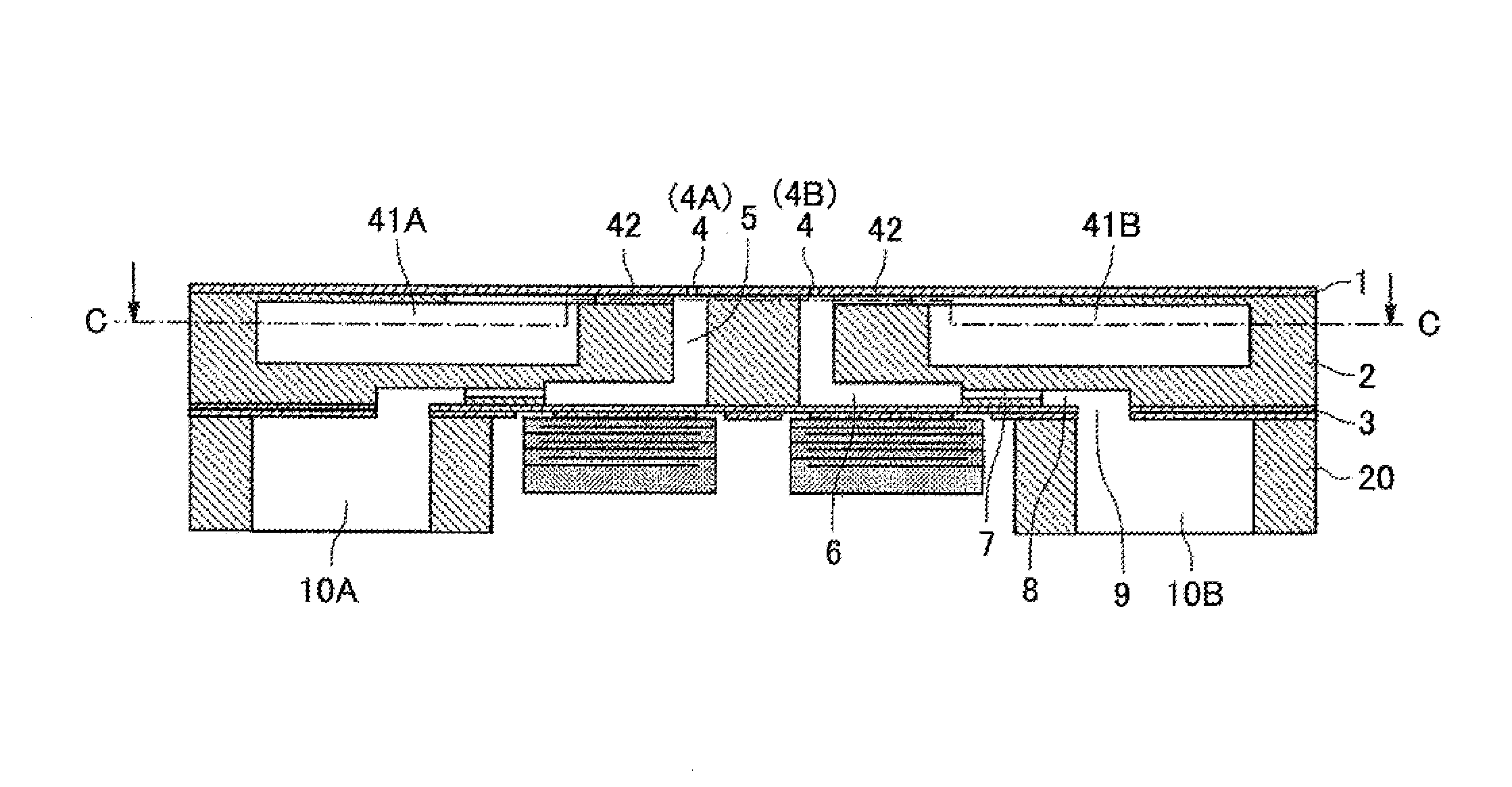
[0056]In the present embodiment, the nozzle plate 1 includes four nozzle lines which are two sets of two nozzle lines 4A and 4B including a plurality of nozzles 4 (the same as the second embodiment which will be described later referring to FIG. 9).
[0057]Further, in the channel plate 2, in the side of the nozzle plate 1 which is opposite to the individual liquid chamber 6, there are two circulation channels 41A and 41B (referred to as “circulation channels 41” as described above when 41A and 41B are not distinguished) corresponding to the two nozzle lines 4A and 4B, which circulation channels 41A and 41B are in communication with the corresponding channels 5 and the individual liquid chambers 6 through the circulation resistance portions 42. It should be noted that, although there are two sets of two circulation channels 41A and 41B, in order to make a simple description, only one set of two circulation channels 41A and 41B will be described.
[0058]Further, the two circulation channe...
fourth embodiment
[0096]In the fourth embodiment, the channel plate can be formed with a simple configuration, the height (height in the thickness direction of the circulation channel member) of the circulation channel 41 can be secured, the channel cross-sectional area of the circulation channels 41 can be made larger, and the pressure loss can be reduced.
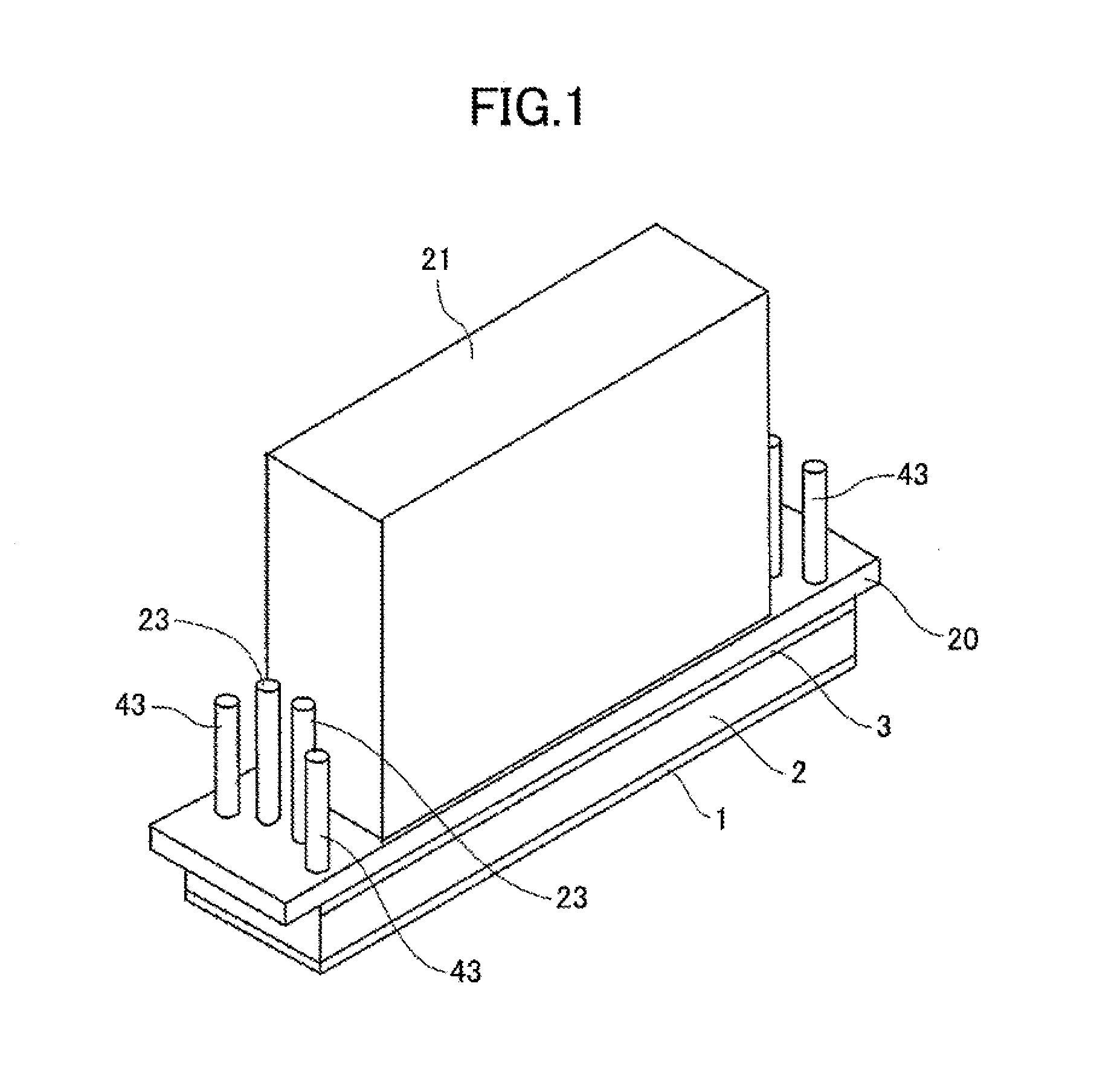
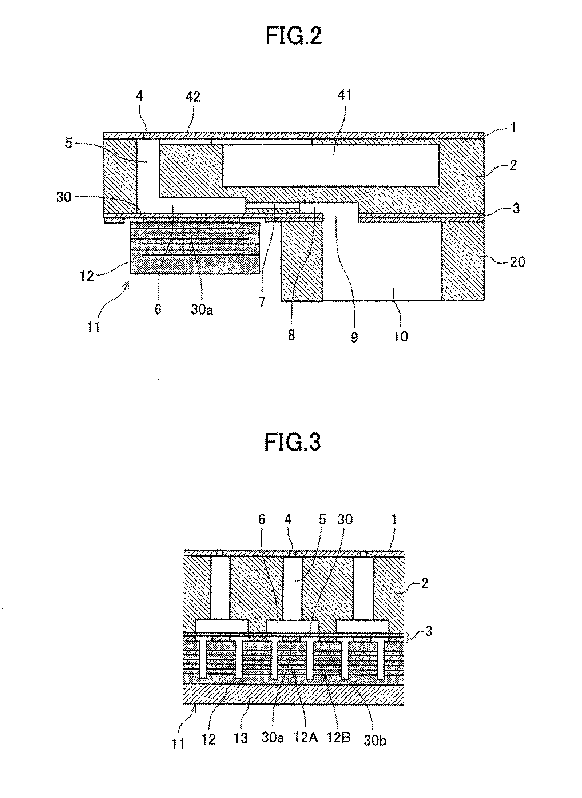
[0097]Next, an example of an apparatus for ejecting liquid including a liquid ejection unit according to the embodiments will be described referring to FIG. 24 and FIG. 25. FIG. 24 is a side view of a mechanical section of an apparatus for ejecting liquid including a liquid ejection unit according to an embodiment of the present invention. FIG. 25 is a plan view of a main section of the mechanical section.
[0098]The apparatus for ejecting liquid is a serial type image forming apparatus. A carriage 433 is supported by a main-guidance rod 431 and a sub-guidance rod 432 which are guidance members bridging laterally between left and right side plates 42...
PUM
 Abstract
Description
Claims
Application Information