Cutter Blade Drive Mechanism, Cutter, and Printer

Active Publication Date: 2016-06-30
SEIKO EPSON CORP
View PDF1 Cites 7 Cited by
  • Summary
  • Abstract
  • Description
  • Claims
  • Application Information

AI Technical Summary

Benefits of technology

[0007]An objective of the present invention is to provide a cutter blade drive mechanism and cutter that can reliably return a cutter blade that cuts media at t

Problems solved by technology

If the movable knife returned to the retracted position is thus offset to the forward position side of the retracted position, and the movable knife is normally covered by a cover when at th

Method used


Image

  • Cutter Blade Drive Mechanism, Cutter, and Printer
  • Cutter Blade Drive Mechanism, Cutter, and Printer
  • Cutter Blade Drive Mechanism, Cutter, and Printer

Examples


Embodiment Construction

[0032]A preferred embodiment of a printer according to the present invention is described below with reference to the accompanying figures.

General Configuration

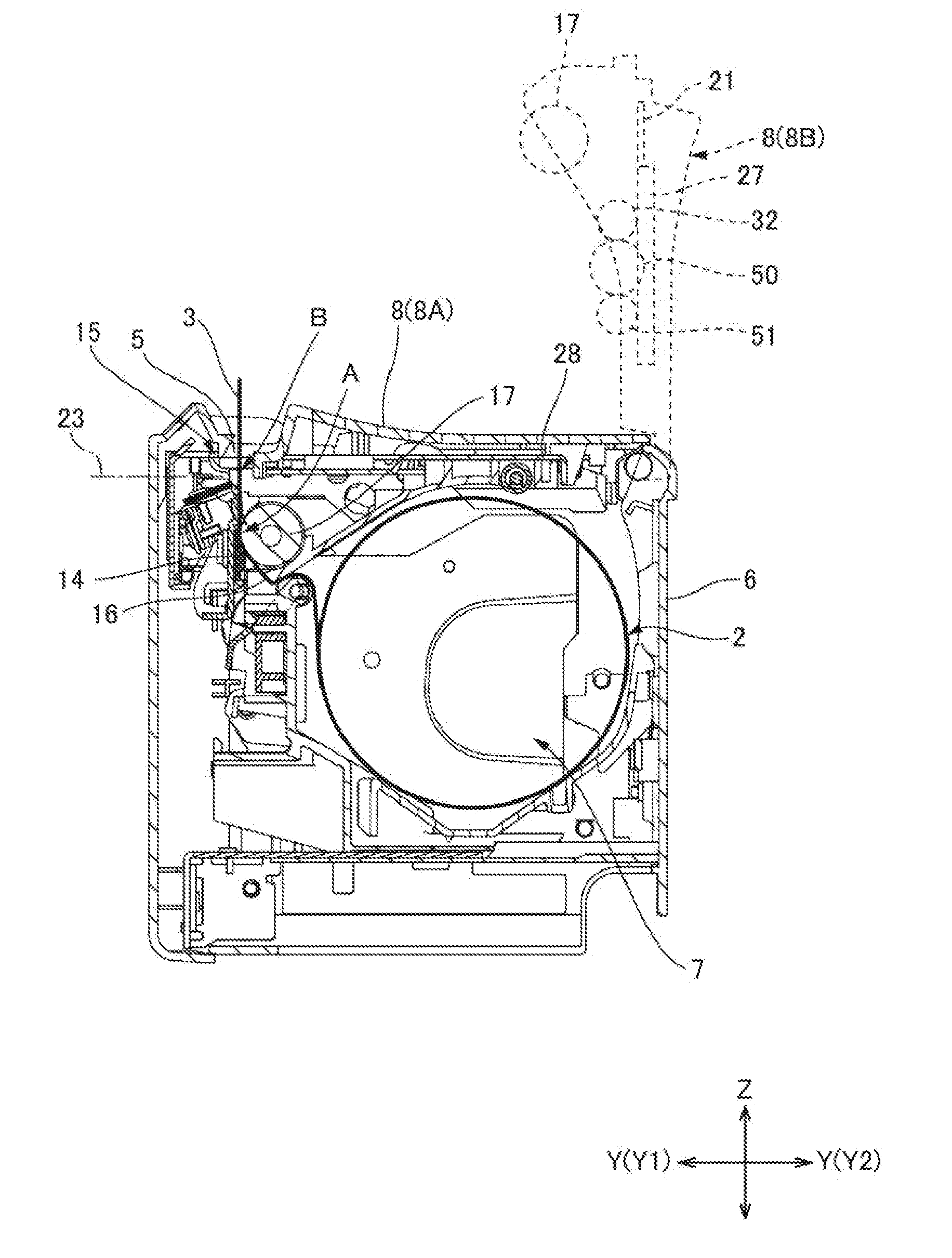
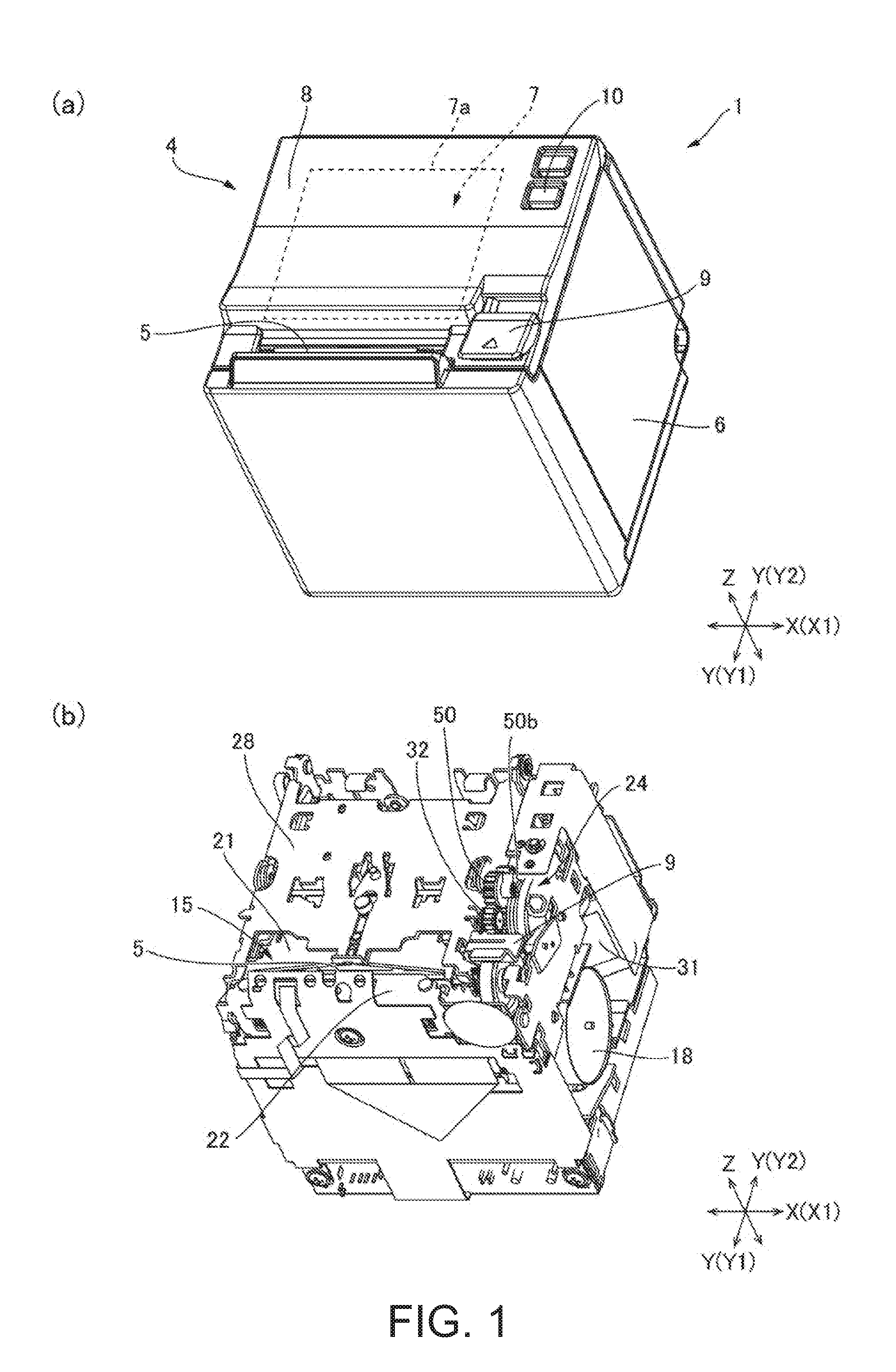
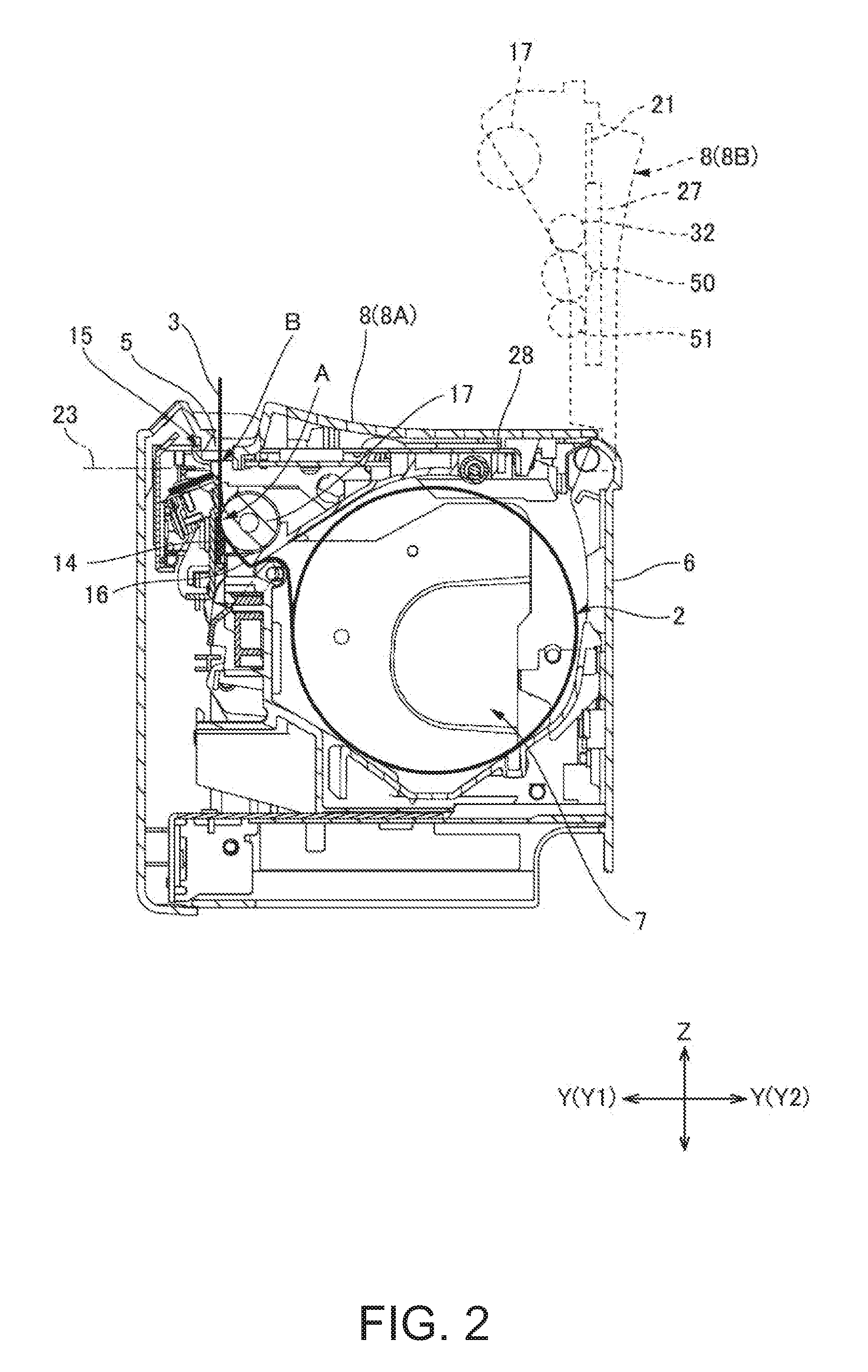
[0033]FIG. 1, view (a) is an oblique view of a printer 1 according to an embodiment of the invention, and FIG. 1, view (b) is an oblique view of the printer 1 in view (a) without the outside case 4. FIG. 2 is a section view of the printer 1 in FIG. 1. The printer 1 in this example is a roll paper printer that prints on recording paper 3 delivered from a paper roll 2. As shown in FIG. 1, the printer 1 has a basically box-like printer case 4. A paper exit 5 from which the recording paper 3 is discharged is formed in the top front part of the printer case 4. The paper exit 5 extends widthwise to the printer 1. Note that three mutually perpendicular axes, a transverse axis X aligned with the printer width, a longitudinal axis Y, and a vertical axis Z, are used below.

[0034]The printer case 4 includes a box-like main case 6, and an...


PUM


Abstract

A cutter blade drive mechanism reliably returns a cutter blade from a forward position to a retracted position. A rotation transfer mechanism 34, which transfers rotation of a drive motor 31 to a drive gear 32, has a cutter blade return gear 50 that meshes with the drive gear 32, a compound gear 40 to which rotation from the drive motor 31 is transferred, and a transfer gear 51 that meshes with the compound gear 40 and the cutter blade return gear 50. While an intermittent teeth part 43a of the compound gear 40 and the transfer gear 51 are meshed, the cutter blade 21 moves to the forward position 21A. When the intermittent teeth part 43a and the transfer gear 51 are not meshed and the compound gear-side protrusion 44b of the compound gear 40 is in contact with a cutter blade return protrusion 50b of a cutter blade return gear 50, the cutter blade return gear 50 rotates in unison with the compound gear 40, the drive gear 32 turns in the opposite direction, and the cutter blade 21 returns to the retracted position 21B.

Description

BACKGROUND[0001]1. Technical Field[0002]The present invention relates to a cutter drive mechanism and to a cutter that cut sheet media by reciprocally moving a cutter blade. The invention also relates to a printer having the cutter.[0003]2. Related Art[0004]A printer with a cutter is described in JP-A-H10-217182. The cutter in JP-A-H10-217182 has cutter blade drive mechanism that drives a cutter blade reciprocally between a forward position where the recording paper is cut and a retracted position separated from the forward position. The cutter blade drive mechanism has a drive motor, two cutter drive gears to which drive power is transferred from the drive motor, and a guide that guides the movable knife in the forward / back direction. The two cutter drive gears are arranged in a perpendicular direction perpendicular to the forward / back direction of motion (or travel) of the movable knife with their axes of rotation perpendicular to the plane of motion of the movable knife. The two ...

Claims


Application Information

Patent Timeline
IPC IPC(8): B41J11/70B26D5/08B26D1/06
CPCB41J11/70B26D5/083B26D1/065B41J29/387B41J11/663
Inventor ISHIDA, TETSUGO
Owner SEIKO EPSON CORP
Why Eureka
Try Eureka