Refrigeration cycle device and refrigerant circulation method

A technology of refrigerant cycle and refrigeration cycle, applied in refrigerators, refrigeration components, refrigeration and liquefaction, etc., can solve problems such as parts damage, oil exhaustion, and reduction in the return of refrigeration oil.

Inactive Publication Date: 2013-01-09
MITSUBISHI ELECTRIC CORP
View PDF14 Cites 6 Cited by
  • Summary
  • Abstract
  • Description
  • Claims
  • Application Information

AI Technical Summary

Problems solved by technology

However, when using compatible refrigerating machine oil dissolved in a liquid refrigerant, such as ether oil, the refrigerating machine oil and the liquid refrigerant are returned to the compressor at the same time, so the return amount of the refrigerating machine oil is reduced, and the oil in the compressor is exhausted. s reason
[0006] In addition, when the flow rate is increased to increase the oil return amount, a large amount of liquid refrigerant flows into the compressor, and the pressure inside the compressor increases due to the compression of the liquid refrigerant, which may cause abnormal stop or the configuration of the compressor. broken parts

Method used


Image

  • Refrigeration cycle device and refrigerant circulation method
  • Refrigeration cycle device and refrigerant circulation method
  • Refrigeration cycle device and refrigerant circulation method

Examples


Embodiment approach 1

[0028] (Structure of Refrigeration Cycle Device 1010)

[0029] refer to Figure 1 to Figure 8 Embodiment 1 will be described.

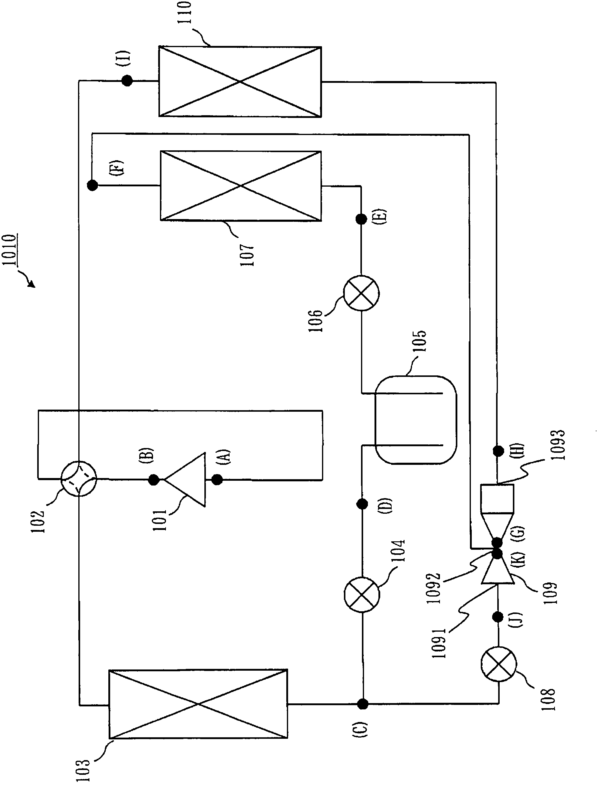
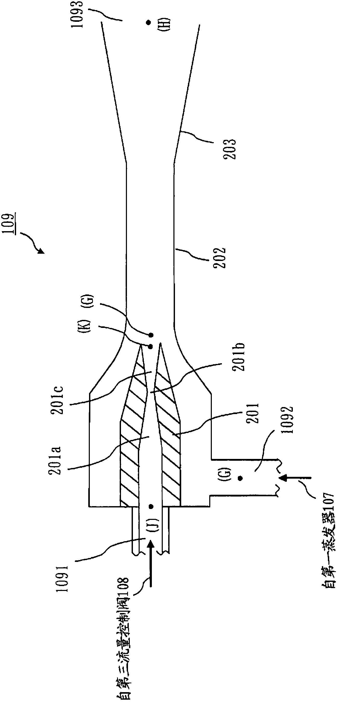
[0030] figure 1 It is a schematic diagram showing the structure of the refrigeration cycle apparatus 1010 of Embodiment 1. The refrigeration cycle device 1010 has an ejector 109 having: a driving refrigerant inflow port 1091 through which a driving refrigerant flows in; a suction refrigerant inflow port 1092 through which a refrigerant is sucked in; The mixed refrigerant outlet 1093 from which refrigerant flows out.

[0031] Refrigeration cycle device 1010 has a first refrigerant passage, which is sequentially connected to compressor 101, condenser 103 as a radiator, first flow control valve 104, refrigerant storage container 105, second The flow rate control valve 106 and the first evaporator 107 are connected to the refrigerant outlet of the first evaporator 107 and the suction refrigerant inlet 1092 of the ejector 109 by piping. In addition, t...

Embodiment approach 2

[0060] refer to Figure 9 ~ Figure 11 Embodiment 2 will be described.

[0061] Figure 9 The refrigeration cycle apparatus 1020 of Embodiment 2 is shown.

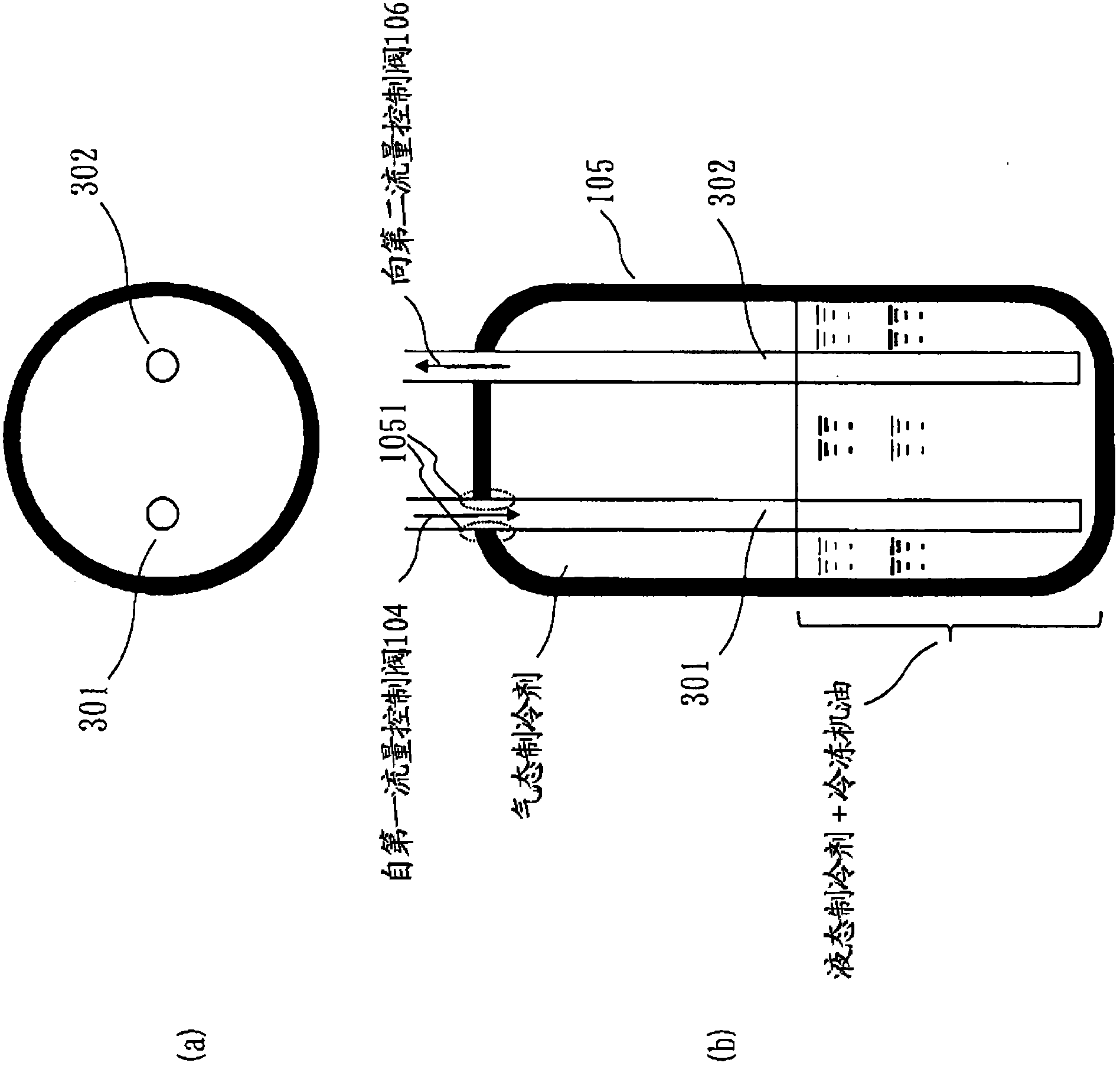
[0062] Figure 10 The structure of the refrigerant storage container 105 of Embodiment 2 is shown. Figure 10 (a) is a plan view of the refrigerant storage container 105 . Figure 10 (b) is a longitudinal sectional view of the refrigerant storage container 105 . In Embodiment 2, the refrigerant piping 310 connecting the second evaporator 110 , the four-way valve 102 , and the suction port 402 of the compressor 101 passes through the inside of the refrigerant storage container 105 . In addition, in showing Embodiment 1 figure 1 , can also be used with Figure 9 Similarly, the refrigerant piping 310 is configured to pass through the refrigerant storage container 105 .

[0063] In addition, an internal heat exchanger 112 is connected between the refrigerant storage container 105 and the second flow rate control valve 1...

Embodiment approach 3

[0069] refer to Figure 12 , Figure 13 The refrigeration cycle device 1030 according to Embodiment 3 will be described. In Embodiment 3, while avoiding depletion of refrigerating machine oil, in an environment where the outside air temperature is low, the suction density of the compressor 101 is low, and the heating capacity is reduced, a compressor with an injection port is used to Increase heating capacity.

[0070] Figure 12 It is a refrigerant circuit diagram of the refrigeration cycle apparatus 1030 of Embodiment 3. The bypass circuit 121 of the refrigeration cycle device 1020 in the second embodiment is connected to the suction pipe of the compressor 101, but the bypass circuit 122 of the refrigeration cycle device 1030 in the third embodiment is connected to the injection port 101-1 of the compressor 101. differ on this point.

[0071] In Embodiment 3, the internal heat exchanger 112 is connected between the refrigerant storage container 105 and the second flow r...


PUM


Abstract

Disclosed is a refrigeration cycle device that is capable of reliably returning refrigerating machine oil to a compressor without being limited by the miscibility or immiscibility of the oil with a refrigerant. The refrigeration cycle device (1010) is equipped with: a first refrigerant course in which the compressor (101), a condenser (103), a first flow control valve (104), a refrigerant storage container (105), a second flow control valve (106), and a first evaporator (107) are connected in that order by piping and in which the refrigerant exit of the first evaporator (107) is connected to the suctioned refrigerant inlet (1092) of an ejector (109) by piping; a second refrigerant course in which the compressor (101) and a second evaporator (110) are connected in that order by piping and in which the refrigerant entrance of the second evaporator (110) is connected to the mixed refrigerant outlet (1093) of the ejector (109) by piping; and a third refrigerant course that diverges from the middle of the piping connecting the refrigerant exit of the condenser (103) and the first flow control valve (104) and in which a third flow control valve (108) and the driving refrigerant inlet (1091) of the ejector (109) are connected in that order by piping.

Description

technical field [0001] The present invention relates to a refrigeration cycle device with an ejector. For example, the present invention provides a highly reliable refrigerating cycle device that can avoid shaft burns due to depletion of refrigerating machine oil in the compressor housing. Background technique [0002] As a conventional refrigeration cycle device with an ejector, in Patent Document 1, an oil return hole is provided on the bottom side of the gas-liquid separator provided at the outlet of the ejector, and a pipe is provided to connect the oil return hole to the compressor. Bypass circuit for suction connection. [0003] With such a structure, the refrigerating machine oil accumulated at the bottom of the accumulator can be returned to the compressor, so that the compressor can be prevented from being burned. [0004] Patent Document 1: Japanese Unexamined Patent Application Publication No. 2002-130874 (Claim 1, FIG. 1 ) [0005] In conventional examples, wh...

Claims


Application Information

Patent Timeline
Patent Type & Authority Applications(China)
IPC IPC(8): F25B1/00F25B5/04F25B43/00
CPCF25B2400/13F25B13/00F25B2400/053F25B31/004F25B41/00F25B2341/0011F25B2400/054F25B5/04
Inventor 东井上真哉野本宗南迫博和
Owner MITSUBISHI ELECTRIC CORP
Why Eureka
Try Eureka