Bicycle having brake with quick release mechanism

a technology of quick release mechanism and bicycle, which is applied in the direction of bicycle brakes, cycle equipment, vehicle components, etc., can solve the problem of difficulty in visually checking if the operating part has been returned to the closed position

Inactive Publication Date: 2014-03-04
SHIMANO INC
View PDF24 Cites 6 Cited by
  • Summary
  • Abstract
  • Description
  • Claims
  • Application Information

AI Technical Summary

Benefits of technology

[0006]Conventionally, a rim brake having a quick release mechanism has been installed in position where a rider can visually check the state of the quick release mechanism and, thus, can easily determine if the operating part has been returned to a closed state. However, when a rim brake having a quick release mechanism is installed on a chain stay, it is difficult to visually check if the operating part has been returned to the closed position.
[0007]One object presented in this present disclosure is to provide a quick release mechanism for a bicycle brake in which an operating part of the quick release mechanism can be reliably returned to a closed position even if a user forgets to return the operating part to the closed position.
[0009]With this bicycle, the contact part provided on the operating part contacts the drive member when the operating part is in the released position. After the contact part contacts the drive member, an operation of the drive member causes the operating part to move from the released position to the closed position. Consequently, even if the operating part is in the released position, the contact part will contact the drive member and the operating part will be moved to the closed position when the drive member operates. Thus, even if a user forgets to return the operating part to the closed position, the operating part can be arranged in the closed position in a reliable fashion.

Problems solved by technology

However, when a rim brake having a quick release mechanism is installed on a chain stay, it is difficult to visually check if the operating part has been returned to the closed position.

Method used


Image

  • Bicycle having brake with quick release mechanism
  • Bicycle having brake with quick release mechanism
  • Bicycle having brake with quick release mechanism

Examples


second embodiment

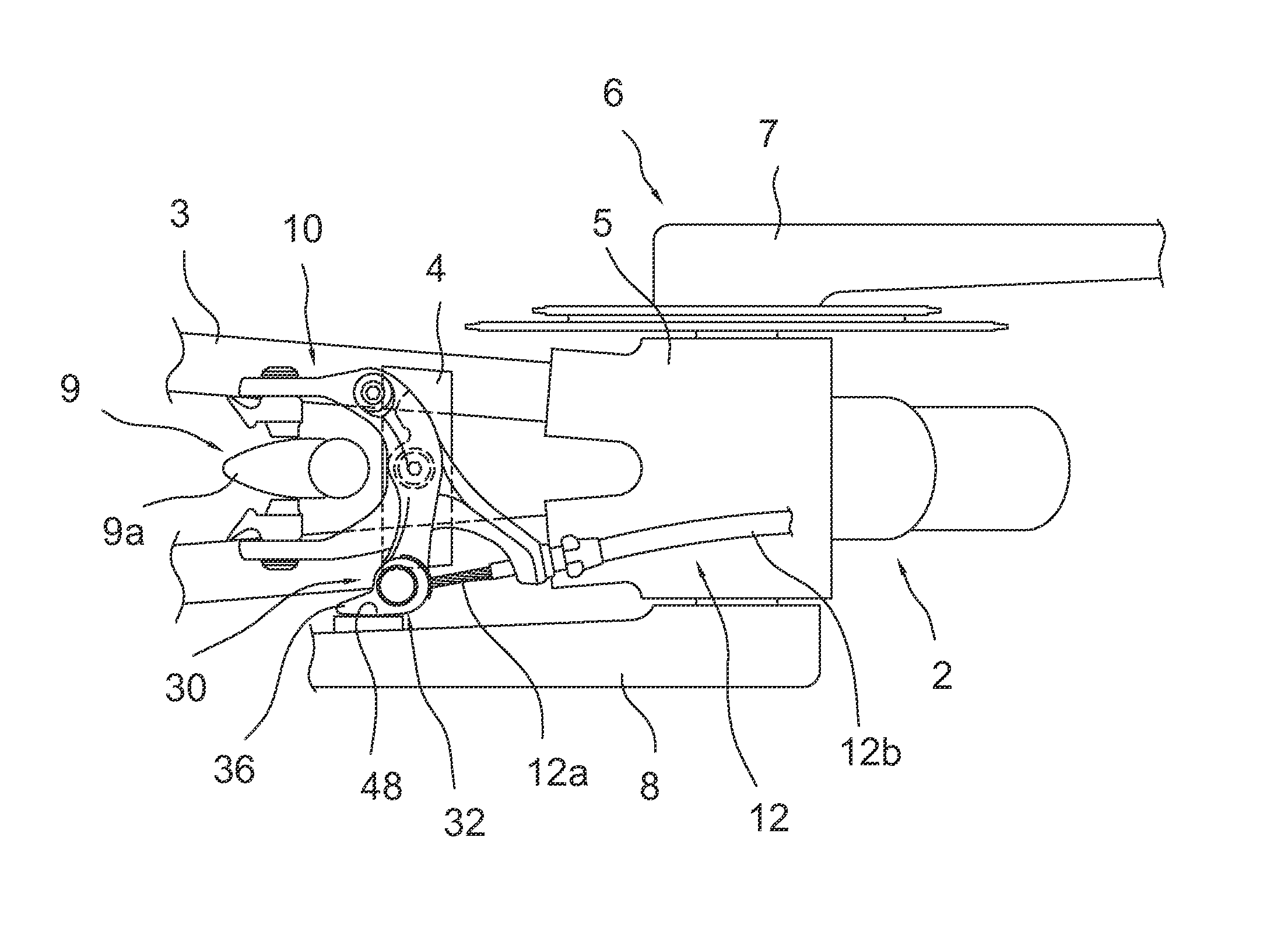
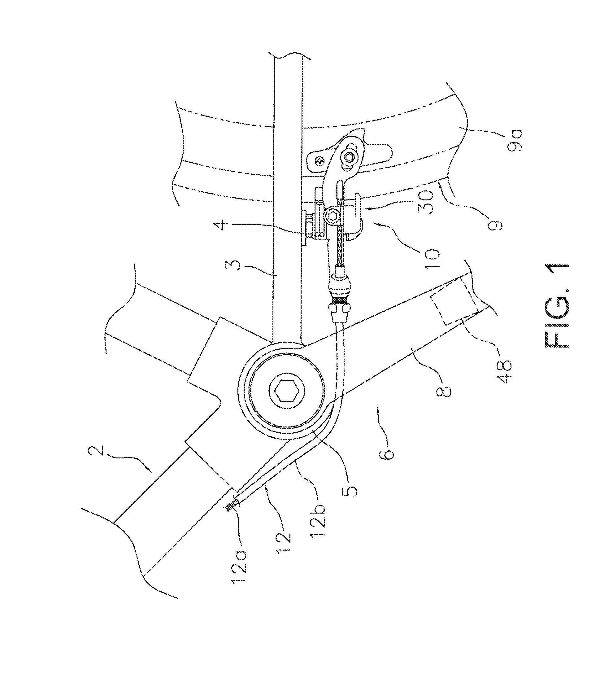
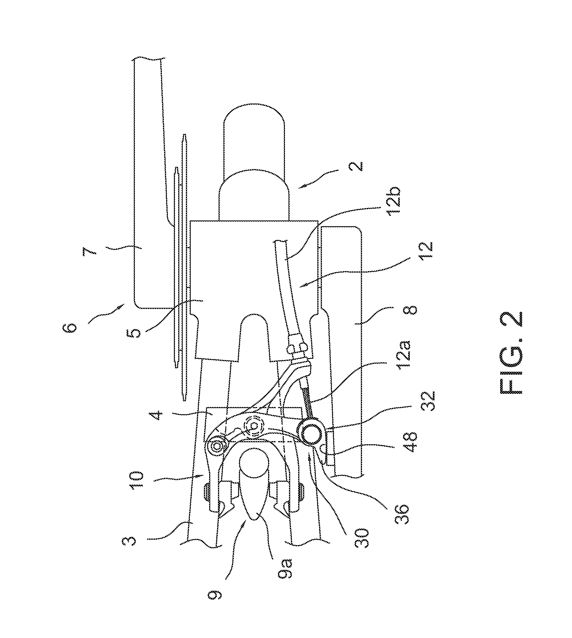
[0052]In the first embodiment, the operating part is the operating lever 32 or 132, but in the second embodiment the operating part is a link mechanism 232 as shown in FIGS. 8A and 8B. The link mechanism 232 is configured to extend and retract between a released position shown in FIG. 8A and a closed position shown in FIG. 8B. The link mechanism 232 is a four-point link mechanism having a pair of first links 232a and a pair of second links 232b. First ends of the first links 232a are rotatably connected together to a back side of one end of the second brake arm 218. A first end of each of the second links 232b is connected to a second end of one of the first links 232a. Second ends of the second links 232b are connected together. The second links 232b are arranged closer to the viewer than the first links 232a in FIGS. 8A and 8B. A restriction wall 218g for restricting the retraction of the second links 232b is formed on a back face of one end of the second brake arm 218. A contact ...

third embodiment

[0054]In the previously explained embodiments, the left crank 8 is presented as an example of a drive member. In the third embodiment, a chain 50 is presented as an example of a drive member. FIGS. 9 and 10 show a caliper brake 310 mounted to a coupling member 314. The caliper brake 310 is basically the same as the caliper brake presented in the first embodiment except that it is inverted about a line of symmetry in comparison with the first embodiment.

[0055]The quick release mechanism 330 is similar to the first embodiment and has a contact part 336 that can contact a step-like portion between an outer link 50a and an inner link 50b arranged between the outer links 50a of the chain 50 when the contact part 336 is in a released position. The mechanism is configured to be arranged in a closed position when it passes a dead point of the biasing member. It is acceptable to provide a cam surface on all links of the chain.

Other Embodiments

[0056]While only selected embodiments have been c...


PUM


Abstract

A bicycle is provided with a frame, a drive member and a bicycle brake. The drive member is movably mounted to the frame for driving the bicycle. The bicycle brake is mounted to the frame. The bicycle brake includes a quick release mechanism that has an operating part and a contact part. The operating part is operatively arranged to be toggled between a closed position and a released position that is separated from the closed position. The contact part is provided on the operating part and configured such that the operating part contacts the drive member while the operating part is positioned at the released position. The contact part is configured such that after the contact part contacts the drive member due to operation of the drive member, the operating part is then moved from the released position to the closed position.

Description

CROSS-REFERENCE TO RELATED APPLICATIONS[0001]This application claims priority under 35 U.S.C. §119 to Japanese Patent Application No. 2011-080693, filed Mar. 31, 2011. The entire disclosure of Japanese Patent Application No. 2011-080693 is hereby incorporated herein by reference.BACKGROUND[0002]1. Field of the Invention[0003]This invention generally relates to a quick release mechanism. More specifically, the present invention relates to a quick release mechanism for a bicycle brake.[0004]2. Background Information[0005]Rim brakes for bicycles are often provided with a quick release mechanism for slightly spreading the brake arms of the rim brake when a wheel will be removed or attached (e.g., see Japanese Examined Utility Model Application Publication No. 64-7119). Japanese Examined Utility Model Application Publication No. 64-7119 discloses a side-pull caliper type rim brake that has a quick release mechanism. A conventional quick release mechanism is configured to slightly open th...

Claims


Application Information

Patent Timeline
Patent Type & Authority Patents(United States)
IPC IPC(8): B62L3/00B62M1/36
CPCB62L1/14
Inventor WATARAI, ETSUYOSHIKARIYAMA, OSAMUNAKAKURA, MASAHIRO
Owner SHIMANO INC
Why Eureka
Try Eureka