
Safety syringe

A technology of safety syringes and injections, applied in the field of syringes, can solve problems such as infection, unstable movement of injection needles, and increased manufacturing costs of safety syringes

Inactive Publication Date: 2004-07-14
SEZ
View PDF0 Cites 6 Cited by
  • Summary
  • Abstract
  • Description
  • Claims
  • Application Information

AI Technical Summary

Problems solved by technology

[0005] However, the conventional safety syringe having the above-mentioned construction has the following disadvantages: when an excessive force exceeding a predetermined magnitude is applied to the injection needle, since the injection needle is fixed through the neck of the barrel while moving vertically and linearly, Injection needle movement is not stable enough
[0007] Conventional safety syringes are somewhat complex in construction, as the injection needle fits securely through the socket which in turn is secured to the adapter
This increases the manufacturing cost of the safety syringe
[0008] There is a risk of infection by introducing contamination into the patient as the fingers of the user holding the safety syringe come into contact with the plunger entering the barrel

Method used


Image

  • Safety syringe
  • Safety syringe
  • Safety syringe

Examples


Embodiment Construction

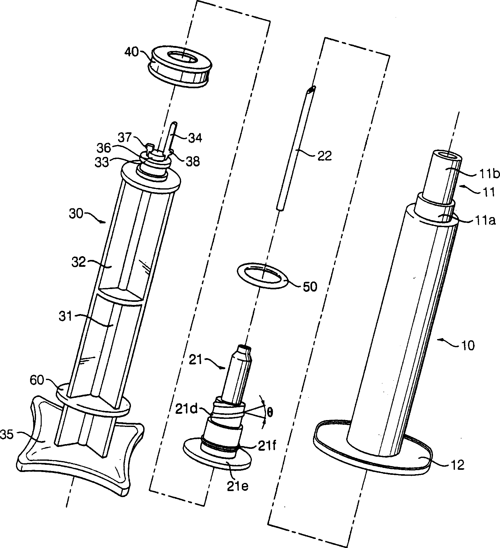
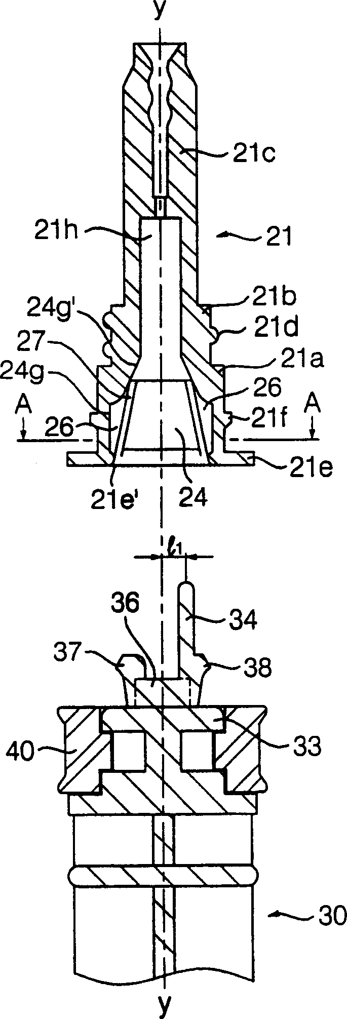
[0035] figure 1 is a sectional view of the safety syringe according to the first embodiment of the present invention; figure 2 is an exploded perspective view of the safety syringe according to the first embodiment of the present invention; image 3 yes figure 1 An enlarged cross-sectional view of the nipple and upper end of the plunger of the safety syringe shown.

[0036] Such as Figure 1-3 As shown, the safety syringe according to the first embodiment of the present invention includes: an elongated syringe 10, which defines a space 10b for containing injection liquid; an injection needle assembly 20, which is connected to the upper end of the syringe 10; and The plunger 30 is partially inserted into the barrel 10 and is movable vertically. The plunger 30 is used to suck the injection liquid into the syringe 10 and discharge the injection liquid contained in the syringe 10 to the outside.

[0037] The upper end of the barrel 10 forms a neck 11 extending upwardly from ...


PUM


Abstract

Disclosed herein is a safety syringe. According to the safety syringe of the present invention, an adapter connected to an injection needle is threadedly coupled with the neck of a cylinder while interposing an O-ring therebetween. Thus, the movement of the injection needle is effectively prevented while in use, and thus the injection needle can be pricked accurately at a desired position of the patient's body. Since the adapter is formed with grooves, whereas a plunger is formed with two protrusions positioned diametrically opposite to each other so as to be inserted into the grooves, the adapter is rotated and then moved downwardly in accordance with the successive rotation and downward movements of the plunger after the adapter is released from the neck of the cylinder. The plunger is formed at its upper surface with a vertical rod extending upwardly from an eccentric position, whereas the adapter is defined with a conical cavity. The upper end of the rod is inserted into the cavity while being bent inwardly. When the injection needle is withdrawn into the cylinder, the injection needle is firmly tilted in a lateral direction due to the strong restoring force of the rod so that it can be collapsed simply against the inner surface of the cylinder. In addition, a circular plate is formed at a certain lower position of the plunger. The circular plate enables the user's fingers gripping the safety syringe not to come into contact with the plunger to be entered into the cylinder, thereby achieving the sanitary use of the safety syringe.

Description

technical field [0001] The present invention relates to syringes, and in particular to a safety syringe, which is configured to allow the injection needle to be retracted into the barrel and destroyed after injecting the liquid medicine, thereby preventing the syringe from being reused, and protecting medical personnel and other personnel from injecting after the injection is completed. Get stuck by a needle and avoid safety-related accidents. Background technique [0002] Safety syringes are known in the art which are configured to allow the injection needle to be retracted into the barrel and destroyed after injection of the medical fluid. [0003] A conventional safety syringe includes: an elongated barrel; a nipple; a socket; a needle; and a plunger. The elongated barrel defines a space for containing injection fluid and has a neck extending upward from its upper end. The nipple is mounted vertically and engages into the neck of the barrel with a sealing ring in betwee...

Claims


Application Information

Patent Timeline
Patent Type & Authority Applications(China)
IPC IPC(8): A61J1/05A61M5/178A61M5/28A61M5/32
CPCA61M5/322A61M2005/3224
Inventor 卜钜星
Owner SEZ
Learn More