Special goods shelf special for automatic stereoscopic warehouse
A technology of three-dimensional warehouses and shelves, applied in the field of automated three-dimensional warehouses, can solve the problems that it is difficult to adapt to the placement of goods at different heights, the size of the compartments on the shelves cannot be adjusted, and waste warehouse space, so as to facilitate picking up goods and avoid shifting or shaking , the effect of convenient placement
- Summary
- Abstract
- Description
- Claims
- Application Information
AI Technical Summary
Problems solved by technology
Method used
Image
Examples
Embodiment 1
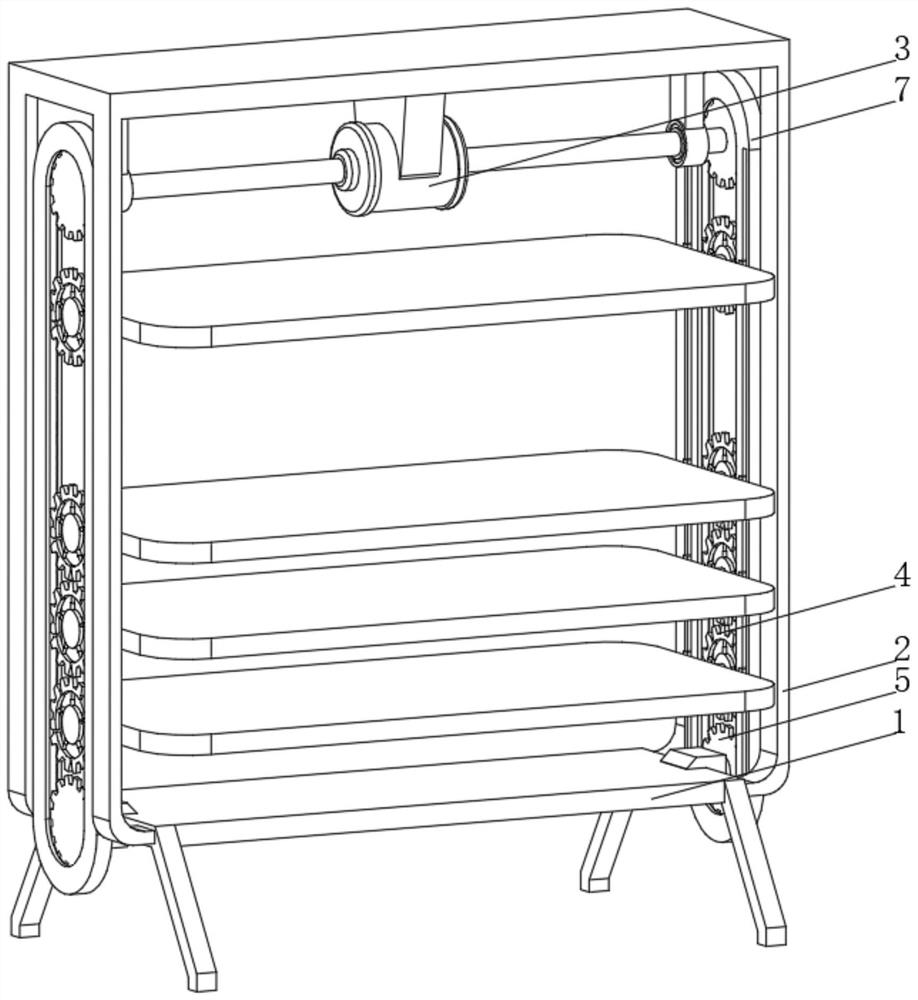
[0034] see Figure 1-3 , the present invention provides a technical solution: a dedicated shelf for an automated three-dimensional warehouse, specifically comprising:
[0035] A fixed base 1, both ends of the fixed base 1 are fixedly connected with a fixed frame 2, and the top of the fixed frame 2 is fixedly connected with a biaxial motor 3 through a fixed plate;
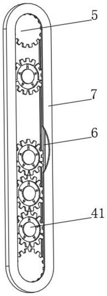
[0036] Climbing frame 7, this climbing frame 7 is provided with two groups and is respectively fixed on the two ends of fixed base 1, and the top of climbing frame 7 is fixedly connected with fixed frame 2;
[0037] Rotating gear 5, this rotating gear 5 is arranged on climbing frame 7 inwall tops and bottoms, and the rotating gear 5 side of climbing frame 7 tops is fixedly connected with the output shaft of biaxial motor 3, and the rotating gear 5 of climbing frame 7 bottoms The side is rotationally connected with the side of the fixed base 1, and the rotating gear 5 on the top and bottom of the inner wall of the c...
Embodiment 2
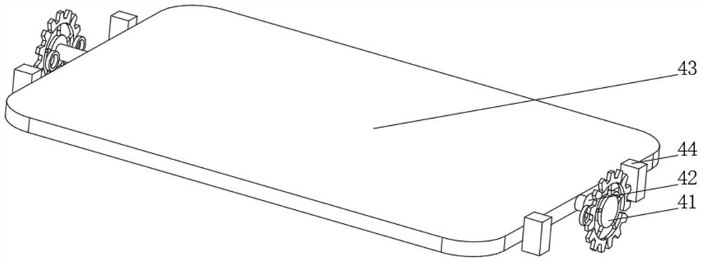
[0044] see Figure 1-4 On the basis of Embodiment 1, the present invention provides a technical solution: the rotating device 41 includes a rotating disc 411, the side of the rotating disc 411 is fixedly connected with a telescopic rod 412, and the end of the telescopic rod 412 away from the rotating disc 411 is fixedly connected with an arc-shaped tooth Bar 413, the side of the curved rack 413 is provided with gear teeth that are compatible with the toothed chain 6, one side of the rotating disc 411 is connected with the adjustment device 42, and the telescopic rod 412 and the curved rack 413 are provided with multiple groups and evenly distributed On the side of the rotating disk 411, the radian of the arc rack 413 is the same as that of the rotating gear 5, and a rotating device 41 is provided. The position of the arc rack 413 can be adjusted by the telescopic rod 412 inside the rotating device 41. When the telescopic rod 412 When shrinking, the arc-shaped rack 413 moves to...
Embodiment 3
[0046] see Figure 1-5 , On the basis of the first and second embodiments, the present invention provides a technical solution: the adjustment device 42 includes an adjustment disc 421, and both sides of the adjustment disc 421 are penetrated and slidably connected with stoppers 422, and the stoppers 422 are located on the adjustment disc 421 One end of the outer side is fixedly connected with a handle 423, the handle 423 is connected to the adjustment disc 421 through an arc spring, one side of the adjustment disc 421 is connected to a rotating column 424 through a bearing, and the two sides of the rotating column 424 are fixedly connected to the part on the side of the stopper 422 There is a fixed block 425, one side of the adjusting disc 421 is fixedly connected with the rotating disc 411, and the end of the rotating column 424 away from the adjusting disc 421 is rotationally connected with the supporting plate 43 through a bearing, and an adjusting device 42 is provided. Wh...
PUM
 Abstract
Description
Claims
Application Information
 - R&D
- Intellectual Property
- Life Sciences
- Materials
- Tech Scout
- Unparalleled Data Quality
- Higher Quality Content
- 60% Fewer Hallucinations
Browse by: Latest US Patents, China's latest patents, Technical Efficacy Thesaurus, Application Domain, Technology Topic, Popular Technical Reports.
© 2025 PatSnap. All rights reserved.Legal|Privacy policy|Modern Slavery Act Transparency Statement|Sitemap|About US| Contact US: help@patsnap.com


