Method and Apparatus for Evaluation of Hydrocarbon-Bearing Reservoirs

a technology of hydrocarbon-bearing reservoirs and hydrocarbon-bearing shale, which is applied in the direction of instruments, survey, borehole/well accessories, etc., can solve the problems of limited hydrocarbon-bearing potential, complex process and unfulfilled understanding, and production of additional gas molecules

Active Publication Date: 2016-06-30
SCHLUMBERGER TECH CORP
View PDF0 Cites 29 Cited by
  • Summary
  • Abstract
  • Description
  • Claims
  • Application Information

AI Technical Summary

Benefits of technology

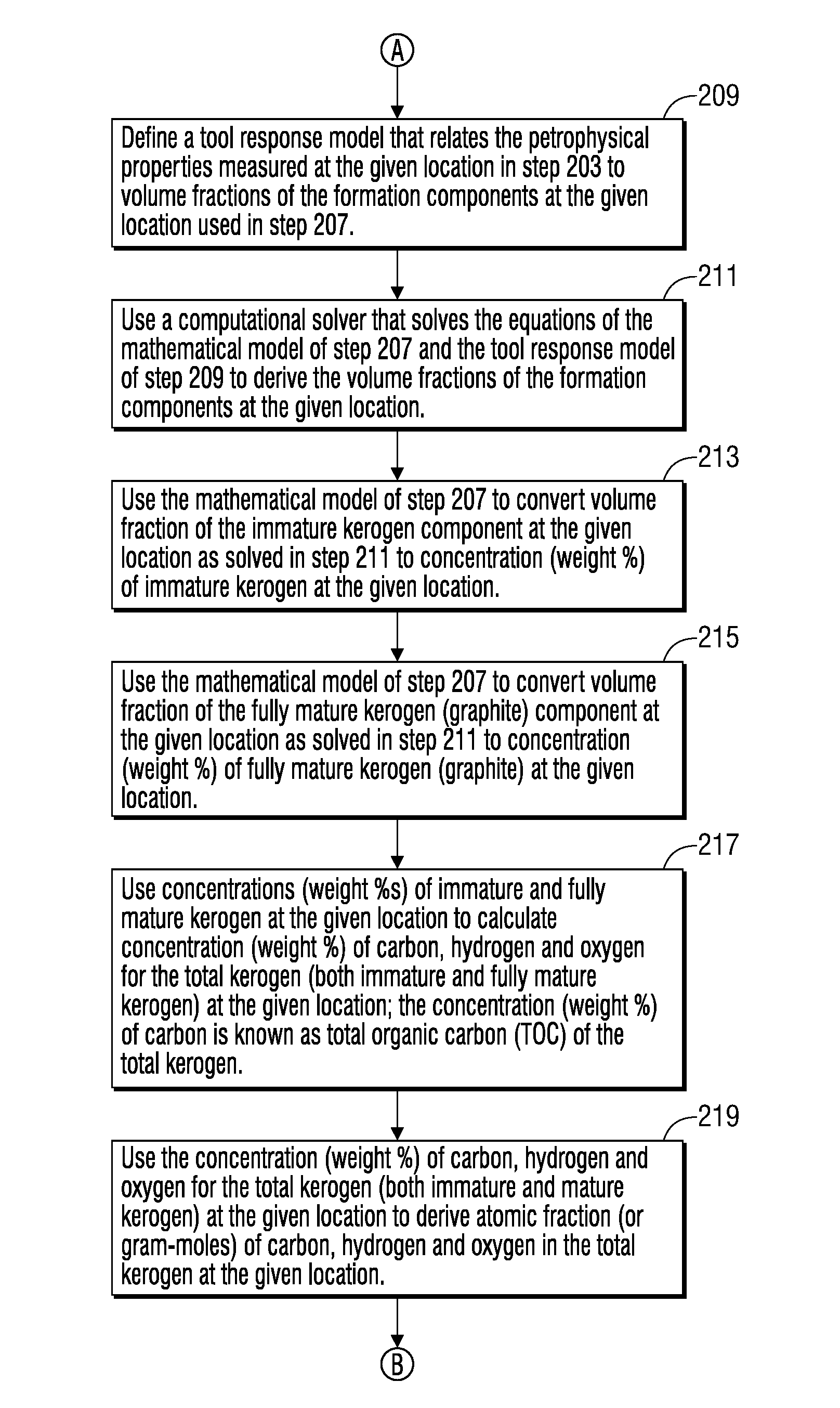
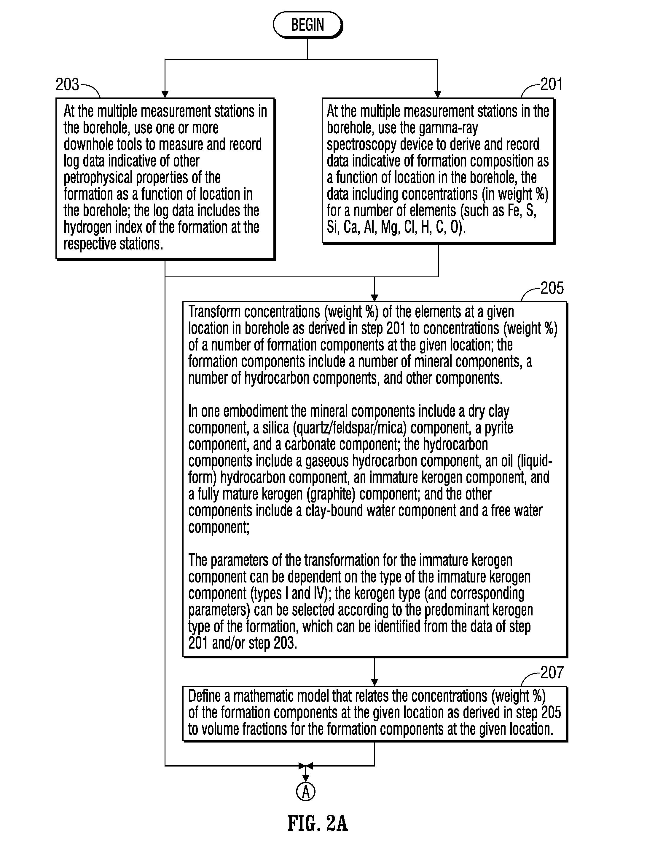
[0023]In one aspect, the present application provides for evaluation of a hydrocarbon-bearing shale formation with the use of a data processing system that defines a response model that relates first data representing measured petrophysical properties of the shale formation at a given location in the shale formation to second data representing volume fractions for a particular set of formation components at the given location in the shale formation. The first data includes hydrogen index at the given location of the shale formation, and the particular set of formation components of the second data include a number of mineral components and a number of hydrocarbon-bearing components. The hydrocarbon-bearing components include an immature kerogen component and a fully mature kerogen component. The data processing system transforms third data representing concentration of a number of chemical elements at the given location in the shale formation to the fourth data representing concentration of the particular set of formation components at the given location in the shale formation. The chemical elements of the third data include at least one of hydrogen, carbon and oxygen. The data proc

Problems solved by technology

It is considered a form of “dead carbon,” with very limited potential for generating hydrocarbons.
This process is complicated and not fully understood; however, the conceptual

Method used


Image

  • Method and Apparatus for Evaluation of Hydrocarbon-Bearing Reservoirs
  • Method and Apparatus for Evaluation of Hydrocarbon-Bearing Reservoirs
  • Method and Apparatus for Evaluation of Hydrocarbon-Bearing Reservoirs

Examples


Embodiment Construction

[0036]It is to be understood that the following disclosure provides many different embodiments, or examples, for implementing different features of various embodiments. Specific examples of components and arrangements are described below to simplify the present disclosure. These are, of course, merely examples and are not intended to be limiting. In addition, the present disclosure may repeat reference numerals and / or letters in the various examples. This repetition is for the purpose of simplicity and clarity and does not in itself dictate a relationship between the various embodiments and / or configurations discussed. Moreover, the formation of a first feature over or on a second feature in the description that follows may include embodiments in which the first and second features are formed in direct contact, and may also include embodiments in which additional features may be formed interposing the first and second features, such that the first and second features may not be in d...


PUM


Abstract

A method and system for evaluation of a hydrocarbon-bearing shale formation employs a data processing system that defines a response model that relates first data representing measured petrophysical properties of the shale formation at a given location to second data representing volume fractions for a particular set of formation components at the given location. The first data includes hydrogen index at the given location, and the particular set of formation components of the second data include a number of mineral components and a number of hydrocarbon-bearing components. The hydrocarbon-bearing components include at least one kerogen component. A computation solver processes the response model along with the first data to solve for the second data. The solved second data representing the volume fraction of the at least one kerogen component is processed to derive at least one ratio that is indicative of kerogen maturity at the given location.

Description

CROSS-REFERENCE TO RELATED APPLICATIONS[0001]This application claims the benefit of and priority to U.S. Provisional Application No. 62 / 098,513, entitled “Method and Apparatus for Evaluation of Hydrocarbon-Bearing Reservoirs,” filed Dec. 31, 2014, the entire disclosure of which is hereby incorporated herein by reference.BACKGROUND OF THE DISCLOSURE[0002]The present application relates to exploration and development of subterranean hydrocarbon-bearing formations. More specifically, the present application relates to evaluation of kerogen rich unconventional hydrocarbon-bearing shale reservoirs.[0003]Shale is an abundant sedimentary rock of extremely low permeability. It is often considered a natural barrier to the migration of oil and gas. In organic rich shales, the oil and gas is generated in place. The organic shale acts as both the source rock and the reservoir. The hydrocarbons can be stored interstitially within the pore spaces between rock grains or fractures in the shale, or ...

Claims


Application Information

Patent Timeline
IPC IPC(8): E21B49/00E21B47/00G06F17/11
CPCE21B49/00E21B47/00G06F17/11G01V99/00
Inventor RASMUS, JOHNLEWIS, RICHARD E.HANDWERGER, DAVIDLAVIGNE, JACK
Owner SCHLUMBERGER TECH CORP
Why Eureka
Try Eureka