Formed hose with different fiber-reinforced regions

a fiber-reinforced region and hose technology, applied electrical apparatus construction details, instruments, etc., can solve the problems of recirculation problems, significantly higher rack inlet temperatures than expected, and become problematic in the direction of hose connection,

Inactive Publication Date: 2016-06-30
INT BUSINESS MASCH CORP
View PDF7 Cites 3 Cited by
  • Summary
  • Abstract
  • Description
  • Claims
  • Application Information

AI Technical Summary

Benefits of technology

[0005]The shortcomings of the prior art are overcome and additional advantages are provided through the provision, in one aspect, of an apparatus which includes a formed hose sized to engageably slide over a hose barb fitting and form a mechanical, fluid-tight connection therewith. The formed hose is a permanently-shaped, partially-deformable, reinforced hose, formed with at least one bend intermediate first and second end regions thereof, and includes: an innermost elastomer layer; a first fiber-reinforcement region of a first fiber-reinforcement density over the innermost elastomer layer at least at the at least one bend of the formed hose; multiple second fiber-reinforcement regions of a second fiber-reinforcement density over, at least in part, the innermost elastomer layer, with second fiber-reinforcement regions of the multiple second fiber-reinforcement regions being disposed at least at the first and second end regions of the formed hose, wherein the second fiber-reinforcement density is greater than the first fiber-reinforcement density; and wherein the first and second end regions of the formed hose are less radially-deformable than the at least one bend thereof due, at least in part, to the second fiber-reinforcement density of the second fiber-reinforcement regions at the first and second end regions of the formed hose being greater than the first fiber-reinforcement density at the first fiber-reinforcement region at the at least one bend thereof, the second fiber-reinforcement density facilitating providing the mechanical, fluid-tight connection when one of the first end region or the second end region of the formed hose is slid over the hose barb fitting, absent any clamp over the formed hose and hose barb fitting connection.

Problems solved by technology

However, this approach is becoming problematic.
In such installations not only will the room air conditioning be challenged, but the situation may also result in recirculation problems with some fraction of the “hot” air exiting one rack unit being drawn into the air inlet of the same rack or a nearby rack.
This re-circulating flow is often extremely complex in nature, and can lead to significantly higher rack inlet temperatures than expected.

Method used


Image

  • Formed hose with different fiber-reinforced regions
  • Formed hose with different fiber-reinforced regions
  • Formed hose with different fiber-reinforced regions

Examples


Embodiment Construction

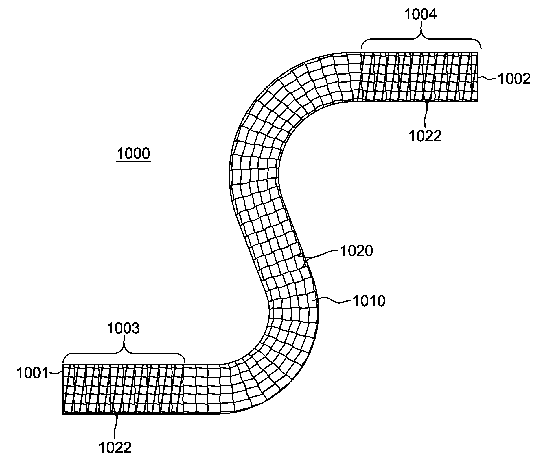
[0027]Generally stated, provided herein are certain novel formed hose configurations and methods of fabrication thereof for facilitating forming a mechanical, fluid-tight connection with a hose barb fitting for, for example, use within a liquid-cooling apparatus providing coolant to one or more electronic subsystems within an electronics rack. The mechanical, fluid-tight connection is formed between a specially-configured, formed hose and a hose barb fitting. The formed hose is a permanently-shaped, partially-deformable, reinforced hose, formed with one or more permanently-curved or bent portions intermediate first and second ends of the hose. The formed hose advantageously includes different fiber-reinforcement regions along its length, with greater fiber-reinforcement density being provided in selected reinforcement regions, including at the first and second end regions of the formed hose. This greater fiber-reinforcement density at the formed hose ends ensures a better mechanical...


PUM

PropertyMeasurementUnit
densityaaaaaaaaaa
lengthaaaaaaaaaa
rotational speedaaaaaaaaaa

Abstract

Formed hose configurations are provided which include an innermost elastomer layer, a first fiber-reinforcement region, and multiple second fiber-reinforcement regions. The first fiber-reinforcement region has a first fiber-reinforcement density, and is disposed, at least in part, at a bend region of the formed hose, and the multiple second fiber-reinforcement regions have a second fiber-reinforcement density, and are disposed at least at the first and second end regions of the formed hose. The second fiber-reinforcement density is greater than the first fiber-reinforcement density, and results in the first and second ends of the formed hose being less radially-deformable than the bend region of the hose. This facilitates providing a mechanical fluid-tight connection with a hose barb fitting when the formed hose is slid over the hose barb fitting, absent any clamp over the formed hose and hose barb fitting connection.

Description

CROSS-REFERENCE TO RELATED APPLICATION[0001]This application is a divisional application of U.S. Ser. No. 14 / 246,208, filed Apr. 7, 2014, entitled “Formed Hose with Different Fiber-Reinforced Regions”, which is hereby incorporated herein by reference in its entirety.BACKGROUND[0002]In many large server applications, processors along with their associated electronics (e.g., memory, disk drives, power supplies, etc.) are packaged in removable drawer configurations stacked within a rack or frame. In other cases, the electronics may be in fixed locations within the rack or frame. Typically, the components are cooled by air moving in parallel air flow paths, usually front-to-back, impelled by one or more air moving devices (e.g., fans or blowers). In some cases it may be possible to handle increased power dissipation within a single drawer by providing greater air flow, through the use of a more powerful air moving device or by increasing the rotational speed (i.e., RPMs) of an existing ...

Claims


Application Information

Patent Timeline
Patent Type & Authority Applications(United States)
IPC IPC(8): F16L11/10F16L11/12
CPCF16L11/12F16L11/10H05K7/20781F16L11/085F16L11/122F16L33/2071F16L33/30F16L35/00Y10T29/49002Y10T29/4994H05K7/20272H05K7/20G06F1/20H02G15/22F16L11/04
Inventor ELLSWORTH, JR., MICHAEL J.SINGH, PRABJIT
Owner INT BUSINESS MASCH CORP
Why Eureka
Try Eureka