Method of manufacturing reactor

Active Publication Date: 2016-06-30
TOYOTA JIDOSHA KK +1
View PDF10 Cites 10 Cited by
  • Summary
  • Abstract
  • Description
  • Claims
  • Application Information

AI Technical Summary

Benefits of technology

[0004]In resin molding in general, injection is carried out in a closed mold by applying pressure on molten resin. In a case of a reactor including a bobbin and a ring core, in which ends of a pair of cylinder portions are connected, there is a risk that edges of openings of the bobbin cylinder portions and an inner circumferential surface of the ring core are displaced and thus make contact with each other when the ring core is pressed from both sides. When highly pressurized resin is injected in a state where the edges of the openings of the bobbin cylinder portions and the inner circumferential surface of the ring core are displaced and making contact, stress is concentrated on the edges of the openings, and a core or the bobbin may thereby break. The present description provides a suitable method of manufacturing a reactor in which a ring core and a bobbin are covered by a plastic cover. Especially, it provides a technique that prevents the edges of the openings of the bobbin and the inner circumferential surface of the ring core from being displaced and making contact, and prevents the ring core or bobbin from breaking upon injecting the molten resin.
[0006]In a method of manufacturing a reactor disclosed herein, protrusions are provided on the bobbin for preventing breakage of the ring core or the bobbin upon the injection molding of the plastic cover. These protrusions are termed “first protrusions”. The first protrusions are provided on each of the connecting portions of the bobbin at outer sides along a cylinder axis direction. The first protrusions are provided to be in contact with an inner circumferential surface of the ring core. Further, protrusions are also provided on a cavity surface of a mold in which a subassembly of the ring core, the bobbin, and the coils is to be contained and then the plastic cover is to be formed by resin injection. The protrusions provided on the mold are termed “second protrusions”. Each of the second protrusions is provided at a position facing the corresponding first protrusion across the ring core. The method of manufacturing a reactor disclosed herein comprises forming the plastic cover by injecting molten resin into the mold while clamping the ring core by the first and second protrusions.
[0007]According to the method of manufacturing a reactor disclosed herein, the ring core is clamped by the first protrusions and the second protrusions that face each other, so the ring core is supported firmly within the mold. Further, the first protrusions at the both ends of the bobbin cylinder portions make contact with the inner circumferential surface of the ring core, and the bobbin is also supported firmly thereby. Due to this, edges of openings of the bobbin cylinder portions are prevented from being displaced and making contact with the inner circumferential surface of the ring core. As a result of this, the breakage of the ring core or the bobbin upon the injection molding of the molten resin can be prevented. Further details and improvements of the technique disclosed herein will be described below in the “Detailed Description of Invention”.

Problems solved by technology

In a case of a reactor including a bobbin and a ring core, in which ends of a pair of cylinder portions are connected, there is a risk that edges of openings of the bobbin cylinder portions and an inner circumferential surface of the ring core are displaced and thus make contact with each other when the ring core is pressed from both sides.

Method used


Image

  • Method of manufacturing reactor
  • Method of manufacturing reactor
  • Method of manufacturing reactor

Examples


Embodiment Construction

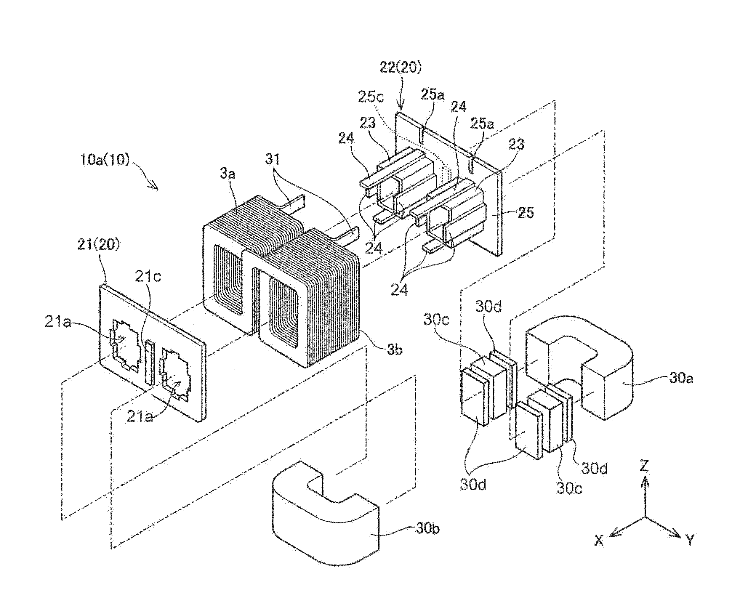
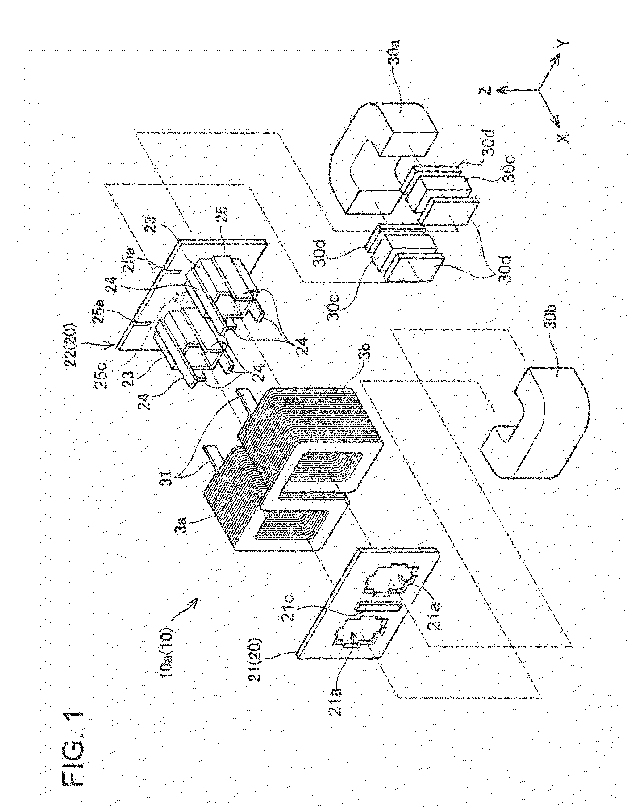
[0012]A method of manufacturing a reactor according to an embodiment will be described with reference to the drawings. A structure of the reactor will be described first, before explaining the manufacturing method thereof. The reactor of the present embodiment is used in a boosting converter that boosts a battery voltage in a driving system of an electric vehicle, for example. A traction motor for the electric vehicle can output power of several ten kilowatts, and a current flowing from the battery can be as large as several ten amperes. With such a large current flowing through the reactor, a flat rectangular wire with a small internal resistance is used as coils therefor.

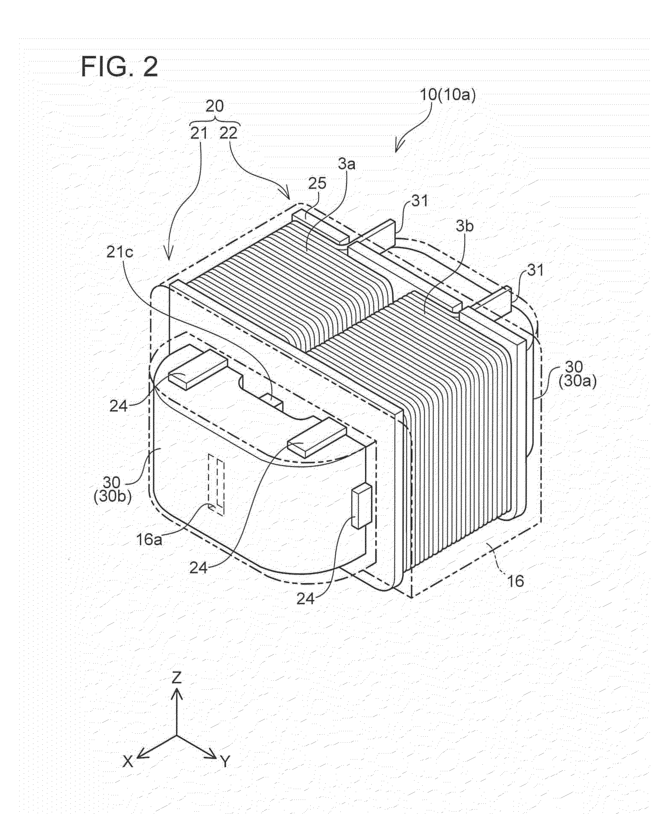
[0013]FIG. 1 is a disassembled perspective view of a reactor 10. Notably, FIG. 1 is a disassembled perspective view of the reactor before a plastic cover is attached. Hereinbelow, the reactor before a plastic cover is attached will be termed a subassembly 10a. FIG. 2 shows a perspective view of the subassembly 10a...


PUM

PropertyMeasurementUnit
currentaaaaaaaaaa
poweraaaaaaaaaa
pressureaaaaaaaaaa

Abstract

Breakage of a ring core or a bobbin upon injection molding of molten resin is to be prevented in a method of manufacturing a reactor including the ring core. A reactor includes a ring core, a bobbin, a pair of coils, and a plastic cover. The bobbin includes a pair of cylinder portions, and flanges connecting ends of the cylinder portions. The reactor is manufactured by following processes. First protrusions that make contact with an inner circumferential surface of the ring core are provided on outer sides of the flanges along a cylinder axis direction. Second protrusions are provided at positions facing the corresponding first protrusions across the ring core are provided on a cavity surface of a mold that forms the plastic cover by injection molding. The plastic cover is formed by injecting molten resin into the mold while clamping the ring core by the first and second protrusions.

Description

CROSS-REFERENCE TO RELATED APPLICATION[0001]This application claims priority to Japanese Patent Application No. 2014-262735 filed on Dec. 25, 2014, the contents of which are hereby incorporated by reference into the present application.TECHNICAL FIELD[0002]The present invention relates to a method of manufacturing a reactor in which a ring core and a bobbin are covered by a plastic cover.DESCRIPTION OF RELATED ART[0003]A reactor in which a ring core, a bobbin, and a coil are covered by a plastic cover is known. Japanese Patent Application Publication No. 2010-118611 discloses an example of such a reactor. The ring core includes a pair of straight portions. Each of the pair of cylinder portions provided on the bobbin cover the corresponding straight portion of the ring core. The pair of cylinder portions are connected to each other by their ends. A coil is disposed on each cylinder portion. The plastic cover is formed by pouring molten resin into a mold in which a subassembly of the ...

Claims


Application Information

Patent Timeline
Patent Type & Authority Applications(United States)
IPC IPC(8): H01F41/00
CPCH01F41/005H01F27/022H01F27/306H01F27/324H01F37/00
Inventor MIYAUCHI, HIROYUKIHIRATA, SHUICHIOKADA, TAKESHIITO, SATOSHIHARA, KENGO
Owner TOYOTA JIDOSHA KK
Why Eureka
Try Eureka