Charging method and charging device

a charging device and charging method technology, applied in parallel/serial switching, indicating/monitoring circuits, transportation and packaging, etc., can solve the problems of not equalizing the voltage of plural cells in parallel connection, and difficulty in accurately reducing the power source voltage to a target value during constant voltage charging, so as to improve the accuracy of voltage value

Inactive Publication Date: 2016-06-30
TOYOTA JIDOSHA KK
View PDF7 Cites 8 Cited by
  • Summary
  • Abstract
  • Description
  • Claims
  • Application Information

AI Technical Summary

Benefits of technology

[0023]In the charging device according to the invention, the positive electrode terminal voltage measuring pin and the negative electrode terminal voltage measuring pin are respectively detached from the positive electrode terminal and the negative electrode terminal ahead of the positive electrode terminal conductive pin and the negative electrode terminal conductive pin when the pins are displaced with respect to the cell. Accordingly, the energization is stopped at a time point that the voltage can no longer be measured. In this way, short circuits of the positive electrode terminal conductive pin and the negative electrode terminal conductive pin can be prevented.
[0024]According to the invention, the charging method and the charging device capable of improving the accuracy of the voltage value during the constant voltage charging can be provided.

Problems solved by technology

However, since only the one power source is used, such a problem that it is difficult to accurately reduce the power source voltage to a target value during the constant voltage charging occurs.
Accordingly, such a problem that voltages of the plural cells are not leveled in the parallel connection also occurs.

Method used


Image

  • Charging method and charging device
  • Charging method and charging device
  • Charging method and charging device

Examples


embodiment 1

[0048]A description will hereinafter be made on an embodiment of the invention with reference to the drawings.

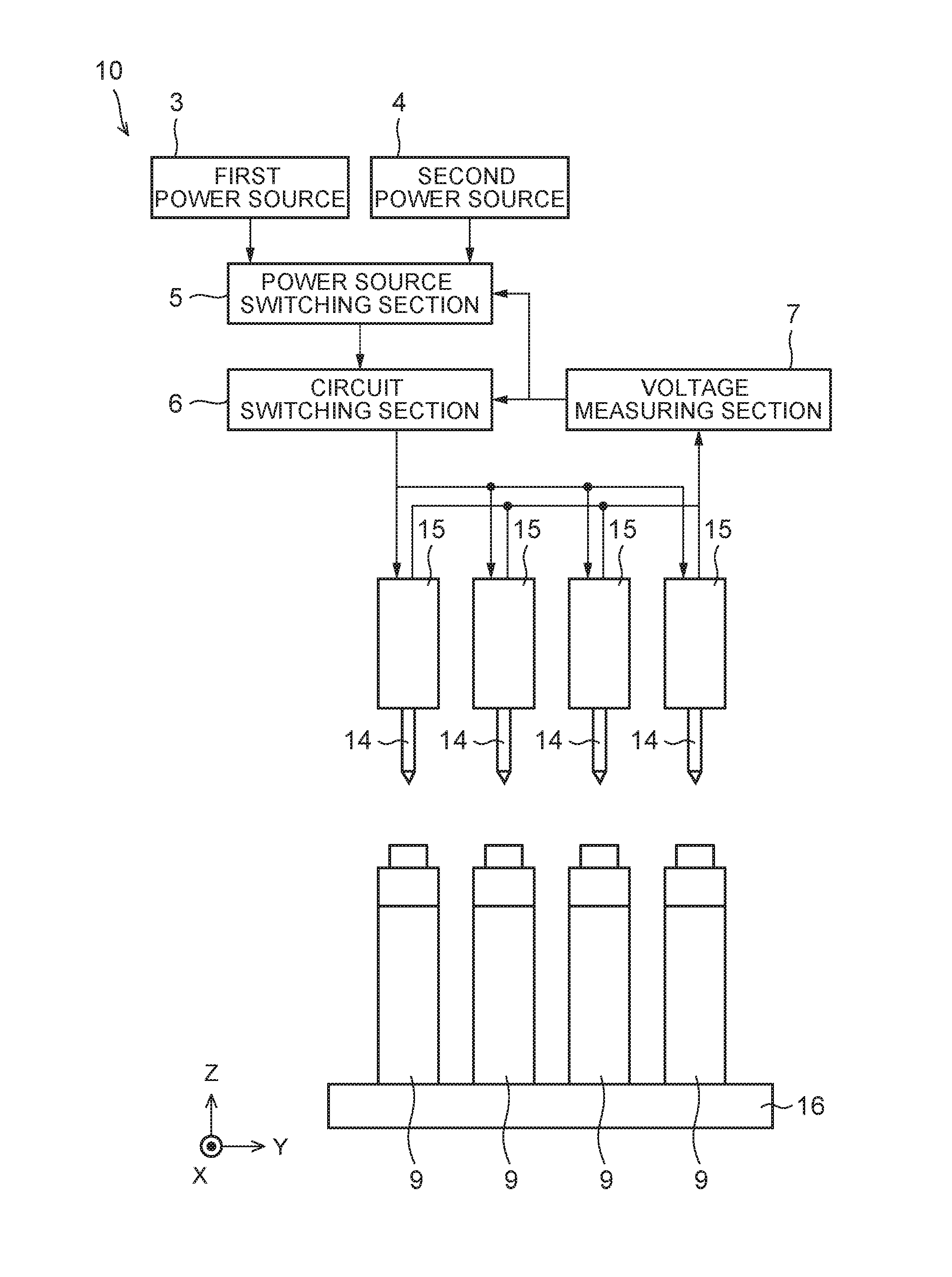
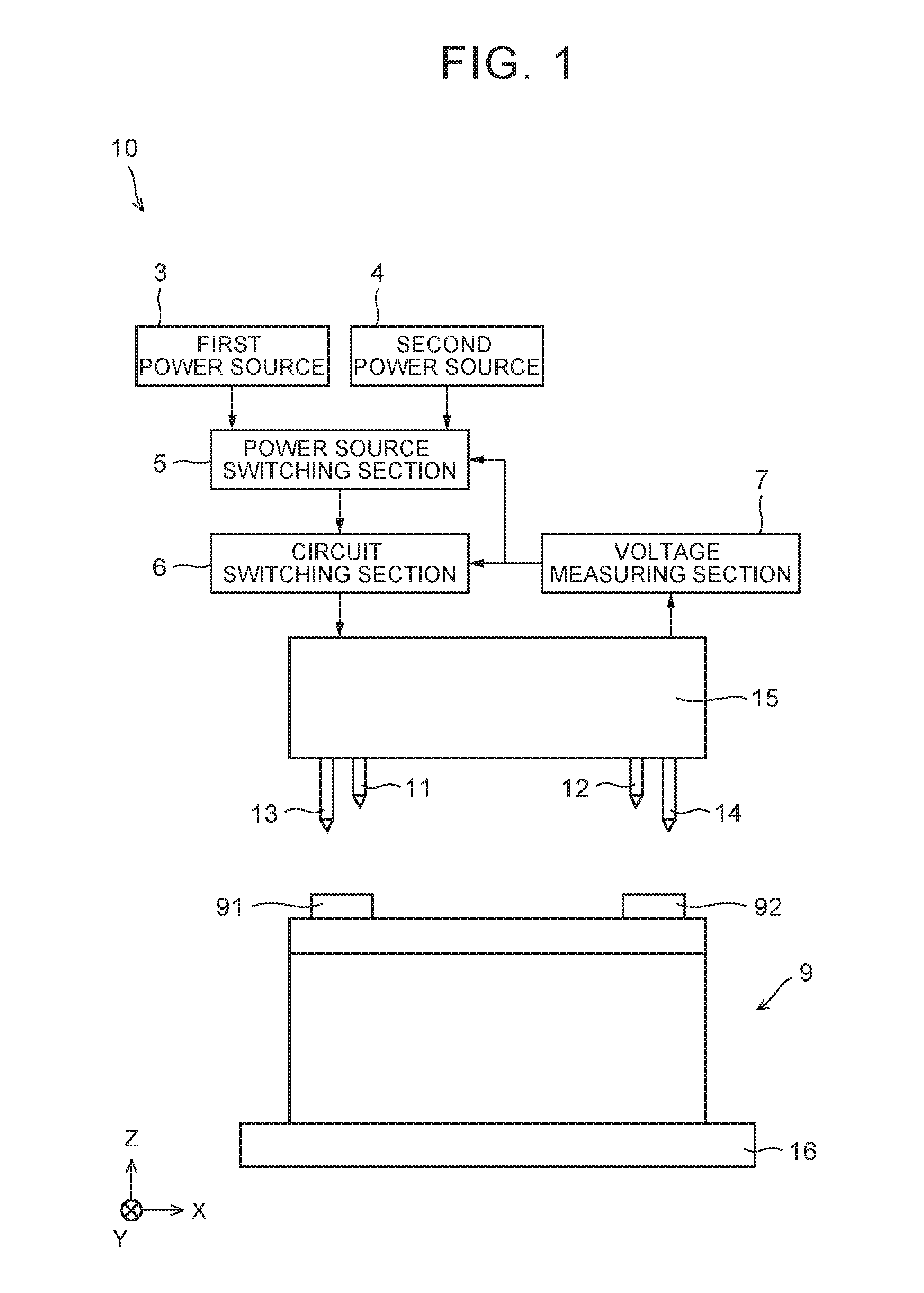
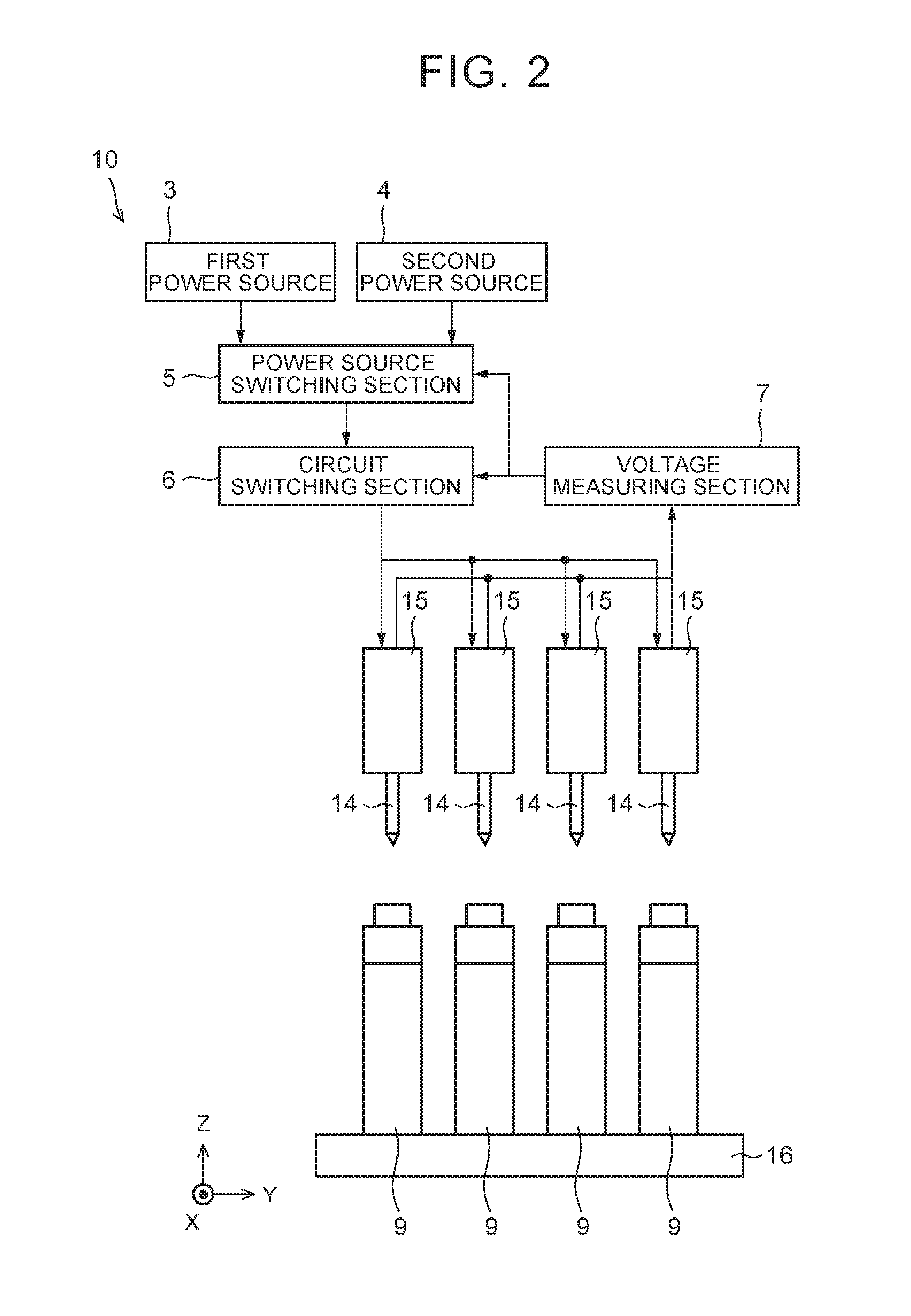
[0049]As shown in FIG. 1 and FIG. 2, a charging device 10 has a positive electrode terminal conductive pin 11, a negative electrode terminal conductive pin 12, a positive electrode terminal voltage measuring pin 13, a negative electrode terminal voltage measuring pin 14, a pin holding section 15, a first power source 3, a second power source 4, a power source switching section 5, a circuit switching section 6, and a voltage measuring section 7. A secondary battery cell 9 has a positive electrode terminal 91 and a negative electrode terminal 92. The positive electrode terminal 91 and the negative electrode terminal 92 are arranged on a terminal surface of the cell 9.

[0050]The charging device 10 charges the cell 9 by connecting the positive electrode terminal 91 and the negative electrode terminal 92 of the cell 9 to the first power source 3 or the second power source 4 and ap...

example

[0083]An example in which the four cells 9 (No. 1 to No. 4) were charged by using the charging device 10 according to this embodiment will be described. As shown in FIG. 9, the four cells 9 were connected in series and were subjected to the constant current charging by the first power source 3. FIG. 11 is a chart of a relationship between time and the voltage when the serial constant current charging was conducted. In FIG. 11, when one of the plural cells 9 reached the specified reference voltage, the constant current charging was stopped. Thereafter, the voltage difference among the plural cells 9 was measured, and it was determined that the voltage difference among the four cells 9 is smaller than the specified value.

[0084]After one of the cells 9 reached the reference voltage, as shown in FIG. 10, the cells 9 were connected in parallel and were subjected to the constant voltage charging by the second power source 4. FIG. 12 is a chart of a relationship between the time and the vo...


PUM


Abstract

A charging method of a secondary battery having plural cells includes: connecting the plural cells in series and conducting constant current charging by a first power source; measuring voltages of the plural cells; and connecting the plural cells in parallel and conducting constant voltage charging by a second power source, a voltage of which is lower than a voltage of the first power source, in the case where a measured voltage difference among the plural cells is smaller than a specified value.

Description

INCORPORATION BY REFERENCE[0001]The disclosure of Japanese Patent Application No. 2014-262684 filed on Dec. 25, 2014 including the specification, drawings and abstract is incorporated herein by reference in its entirety.BACKGROUND OF THE INVENTION[0002]1. Field of the Invention[0003]The invention relates to a charging method and a charging device.[0004]2. Description of Related Art[0005]As a charging method of a secondary battery, for example, a charging method described in Japanese Patent Application Publication No. 2010-63197 (JP 2010-63197 A) has been known. In the charging method described in JP 2010-63197 A, plural cells are connected to one power source and can be switched between a serial connection and a parallel connection by plural switches. In the charging method described in JP 2010-63197 A, the plural cells are connected in series and are subjected to serial constant current charging with a high voltage. Then, the plural cells are connected in parallel and are subjected...

Claims


Application Information

Patent Timeline
Patent Type & Authority Applications(United States)
IPC IPC(8): H02J7/00
CPCH02J7/0024H02J7/007H02J7/0021H02J7/0022H02J7/0016H02J7/0036H02J7/0048
Inventor MINAKUCHI, AKIOMORI, HIDETO
Owner TOYOTA JIDOSHA KK
Why Eureka
Try Eureka