Method and device for determining phase currents and an excitation current of an electrical machine, and motor system

a technology of phase current and excitation current, which is applied in the direction of motor/generator/converter stopper, dc motor speed/torque control, dynamo-electric converter control, etc., can solve the problem of increasing losses, reducing the degree of efficiency, and requiring additional field winding. the effect of increasing circuit complexity

Inactive Publication Date: 2016-07-07
ROBERT BOSCH GMBH
View PDF4 Cites 7 Cited by
  • Summary
  • Abstract
  • Description
  • Claims
  • Application Information

AI Technical Summary

Benefits of technology

[0033]The current measurement apparatus can comprise a measurement amplifier circuit and an analog / digital converter. Furthermore, a minimum time variable of each measurement window can be given by a sum of a minimum dead time of switching elements of the driver circuit, a minimum settling time of the measurement amplifier circuit and a minimum sampling time of the analog / digital converter.

Problems solved by technology

Electrical machines of this kind are highly suitable for many applications, but at high rotation speeds have the disadvantage that the field attenuation required in this case leads to an increase in losses and therefore to a reduction in the degree of efficiency.
The additional field winding typically requires increased circuit complexity.
Furthermore, rapid and reliable measurement of the phase currents through the phase windings and of the field current is required in order to regulate and drive both the phase windings and the field windings, this resulting in additional expenditure.

Method used


Image

  • Method and device for determining phase currents and an excitation current of an electrical machine, and motor system
  • Method and device for determining phase currents and an excitation current of an electrical machine, and motor system

Examples


Embodiment Construction

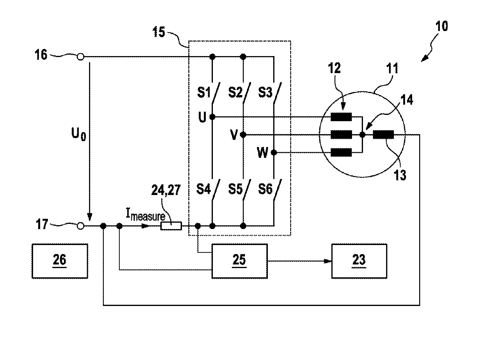
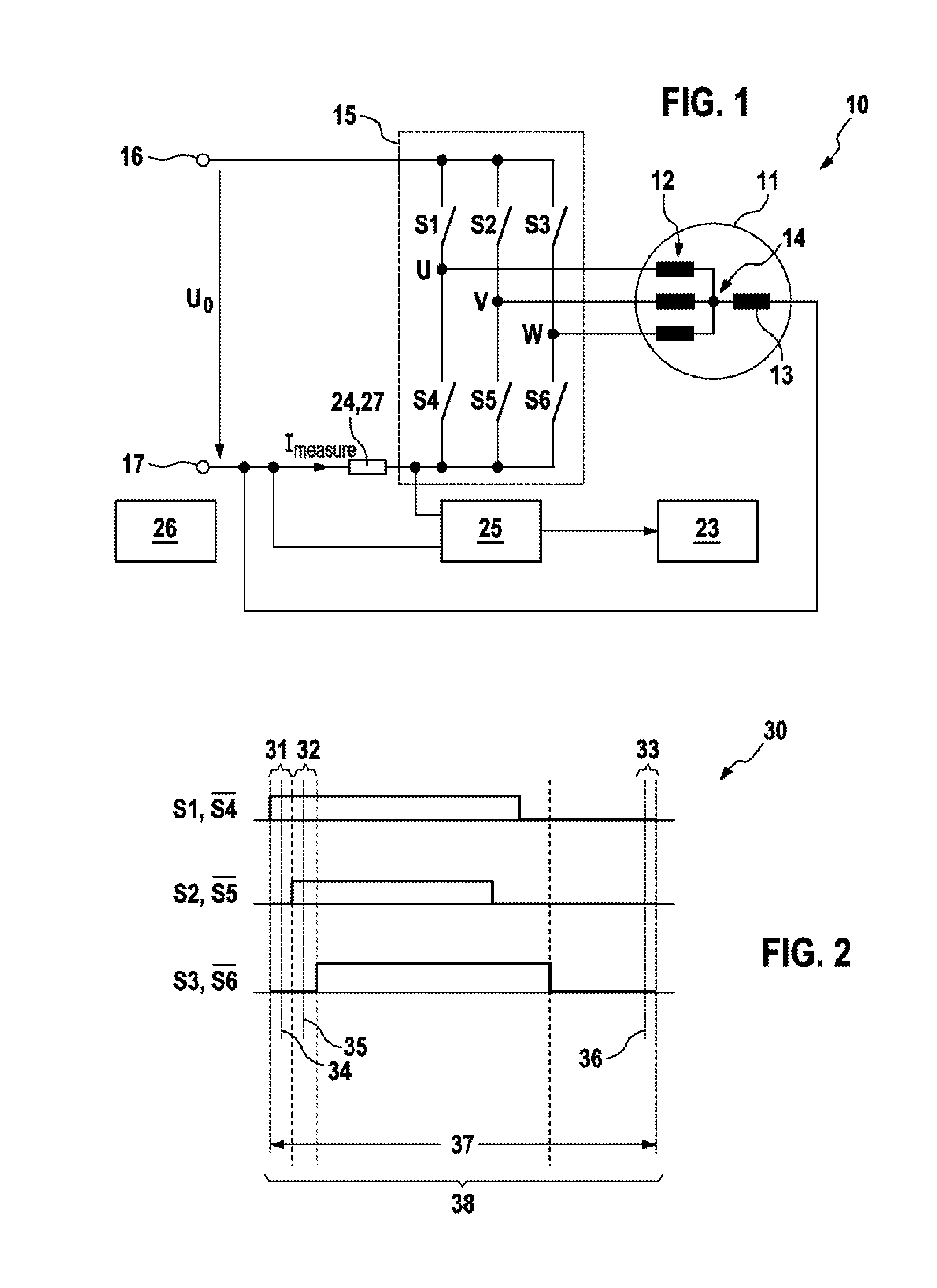
[0038]FIG. 1 schematically illustrates a motor system 10 comprising an electrical machine. The motor system 10 has a three-phase machine with hybrid excitation as electrical machine 11 with three phase windings 12 with the phase connections U, W, V. The phase windings 12 are connected to one another in the electrical machine 11 in star. The electrical machine 11 further has a field winding 13 which serves to generate, or contributes to generating, a magnetic field in the rotor of the electrical machine 11 with hybrid excitation and which is electrically connected to the star point 14.

[0039]The phase windings 12 are supplied with corresponding phase voltages by means of a driver circuit 15, here an inverter with six switches S1 to S6 which are connected to one another in the form of a fully controlled 6-pulse bridge (B6) which is known per se. The switches S1 to S6 of the driver circuit 15 are driven by a drive unit 26, wherein the switches S1 to S3 correspond to the pull-up switches...


PUM


Abstract

The invention relates to a method for determining the phase currents through phase windings (12) and an excitation current through an excitation winding (13) of an electrical machine (11), wherein an excitation winding (13) is connected between a star point (14) of the phase windings (12) and a defined reference potential, the method comprising the following steps: —periodic driving of the electrical machine (11) with a predefined pulse pattern (30); —determining a respective measurement current (Imess) in a plurality of temporal measuring windows (31, 32, 33) of a measuring period (37), wherein the measurement currents (Imess) correspond to currents through one of the phase windings (12) and through one or more parallel connections of a plurality of the phase windings (12); and —determining the phase currents and the excitation current by evaluating the measurement currents (Imess) determined during the measuring period (37).

Description

BACKGROUND OF THE INVENTION[0001]The present invention relates, in general, to a method and to an apparatus for measuring motor currents in an electrical machine.[0002]Electronically commutated electrical machines with permanent magnets, such as permanent-magnet synchronous motors, are common. Electrical machines of this kind are highly suitable for many applications, but at high rotation speeds have the disadvantage that the field attenuation required in this case leads to an increase in losses and therefore to a reduction in the degree of efficiency. In contrast to this, the field attenuation is achieved in a simple manner by reducing the excitation magnetic field in the case of electrical machines with external or hybrid excitation.[0003]In the case of electrical machines with external excitation, the excitation magnetic field is generated with the aid of a separate field winding whereas, in the case of electrical machines with hybrid excitation, the magnetic field is generated b...

Claims


Application Information

Patent Timeline
Patent Type & Authority Applications(United States)
IPC IPC(8): H02P6/32
CPCH02P6/32G01R19/0092H02M7/53875H02P21/22H02M1/0009
Inventor LAMPRECHT, DIRK
Owner ROBERT BOSCH GMBH
Why Eureka
Try Eureka