Cleaning appliance

a cleaning appliance and cleaning technology, applied in the field of cleaning, can solve the problems of inability to completely clean up dust, particulate waste or flocks, time-consuming and labor-intensive, and inconvenient cleaning of floor cleaning appliances, and achieve the effect of high working efficiency

Inactive Publication Date: 2016-07-14
DONGGUAN PHEATON ELECTRONICS TECH
View PDF3 Cites 11 Cited by
  • Summary
  • Abstract
  • Description
  • Claims
  • Application Information

AI Technical Summary

Benefits of technology

[0004]The objective of the present invention is to overcome the defects in the prior art and provide a cleaning appliance which can clean up neatly and has high working efficiency.
[0025]The present invention has the advantages that: the cleaning appliance provided by the present invention adopts a combined structure of the two brush rollers and the dust collector; both rotation directions of the two brush rollers direct towards the suction port; dust, particulate waste or flocks are gathered; the waste is sucked into the dust collector through the suction port between the two brush rollers; and hence the one-time rapid and neat cleaning effect can be achieved. Moreover, dust, other particulate waste or flocks on the floor are all cleaned at once and dust lines will not be retained on the floor, so that the labor intensity can be greatly reduced.

Problems solved by technology

Therefore, the floor cleaning appliance is extremely inconvenient in the process of floor cleaning, is time-consuming and labor-consuming, and cannot completely clean up dust, particulate waste or flocks.

Method used


Image

  • Cleaning appliance
  • Cleaning appliance
  • Cleaning appliance

Examples


embodiment 1

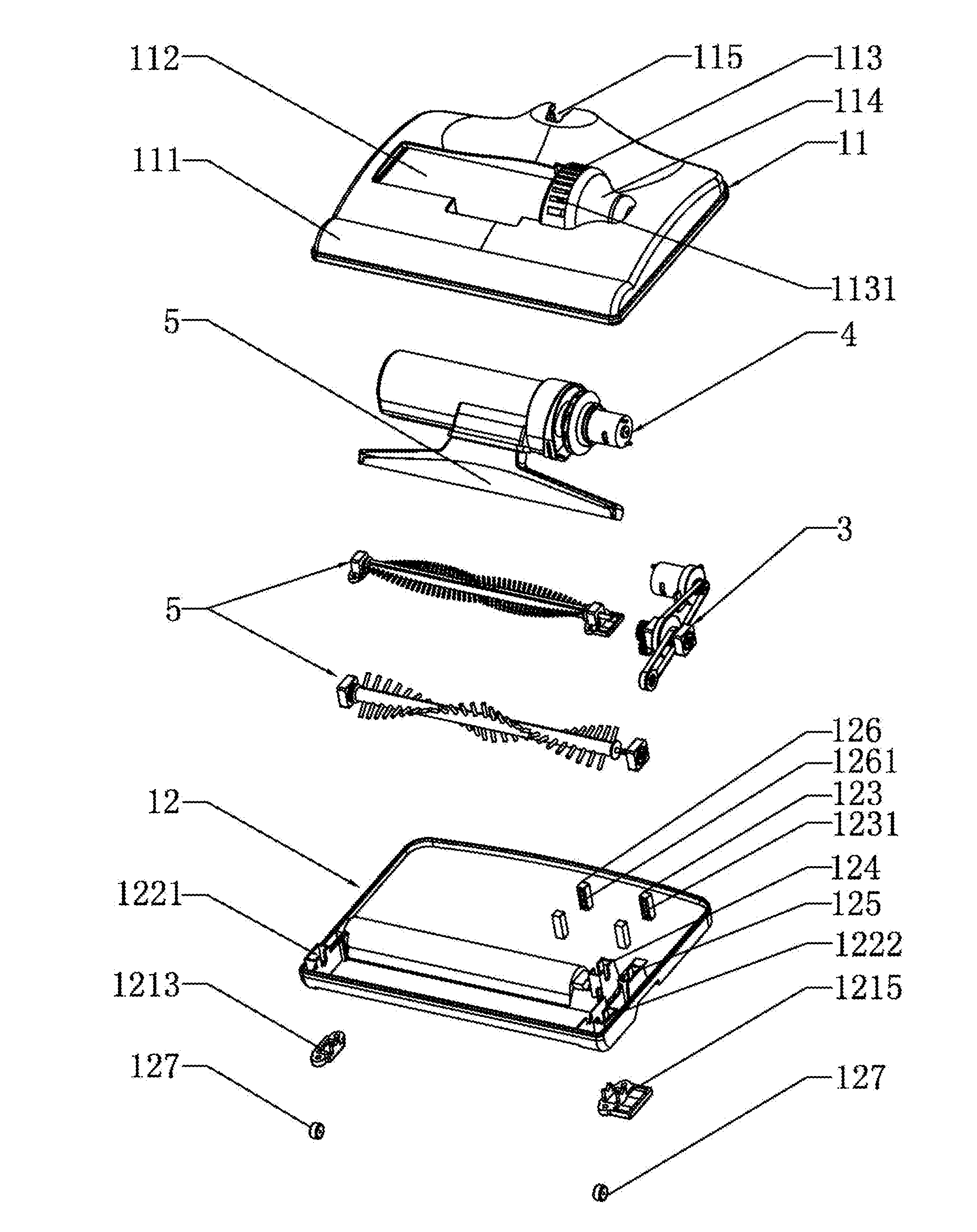
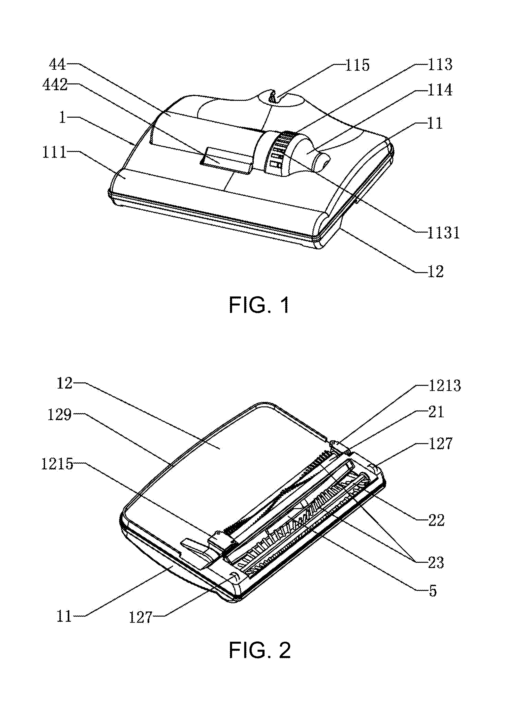
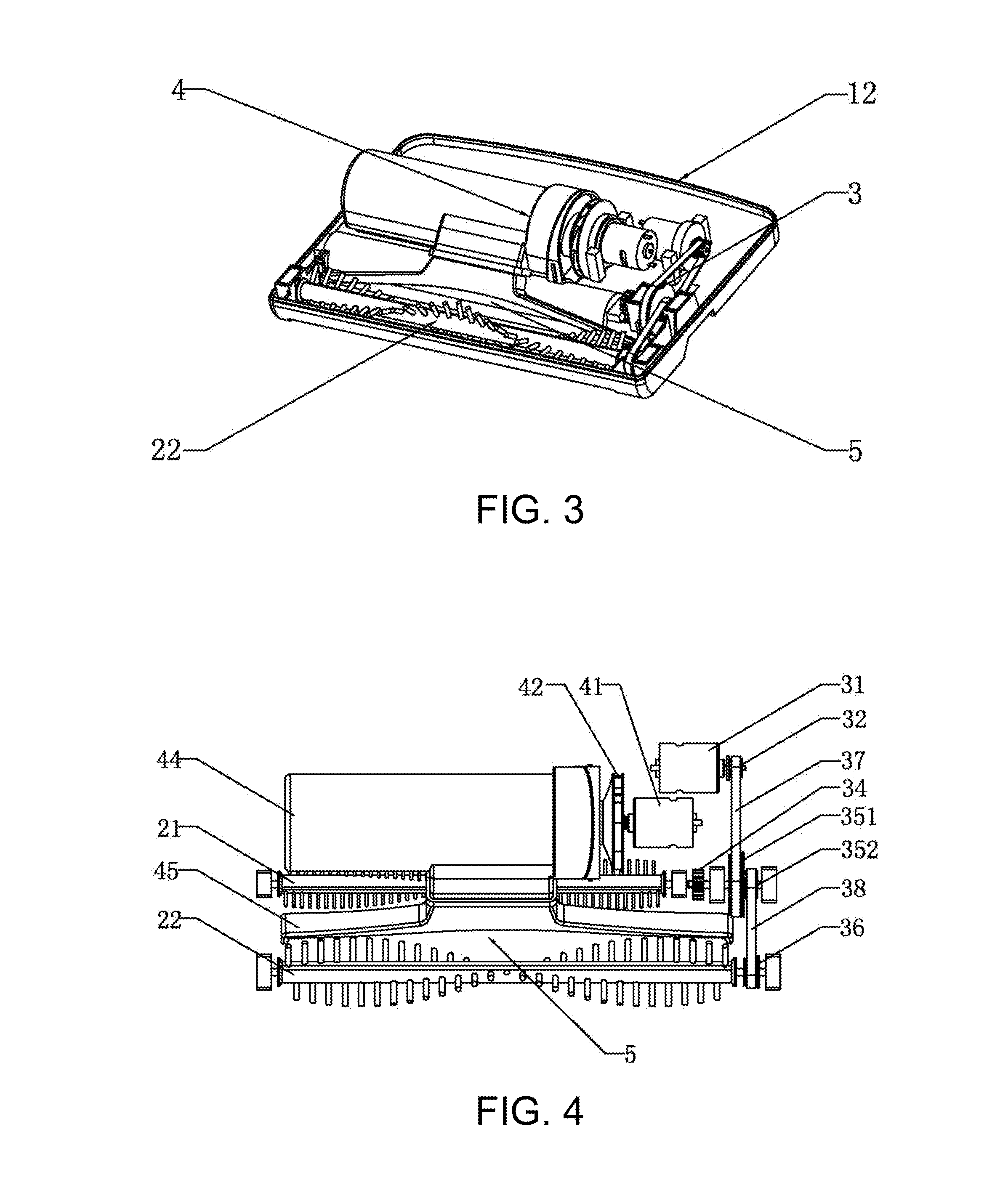
[0042]FIGS. 1 to 13 illustrate the embodiment 1 of the cleaning appliance provided by the present invention, which comprises a cleaning appliance body. The cleaning appliance body includes a housing 1, two brush rollers 2 disposed at the bottom of the housing 1, a drive mechanism 3 disposed in the housing 1 and configured to drive the two brush rollers 2 to rotate, and a dust collector 4 disposed on the housing 1. A suction port 5 of the dust collector 4 is disposed between the two brush rollers 2. Both rotation directions of the two brush rollers 2 direct towards the suction port 5.

[0043]The number of the suction port 5 may also be two or more than two as long as waste can be sucked into the dust collector 4 from the suction port 5. Any apparent replacement made without departing from the concept of the present invention shall fall within the scope of protection of the present invention.

[0044]The cleaning appliance provided by the present invention adopts a combined structure of th...

embodiment 2

[0065]FIG. 14 illustrates the embodiment 2 of the cleaning appliance provided by the present invention. The difference from the embodiment 1 is as follows: a cushion body 128 is disposed at the rear of the bottom of the lower housing 12 and is a cloth cushion or a paper cushion; and the cloth cushion is a steam spray cloth cushion, a water spray cloth cushion or a disinfecting fluid spray cloth cushion. More specifically, a cushion body receiving groove is disposed at the rear of the bottom of the lower housing 12, and the cushion body 128 is embedded into the cushion body receiving groove. The cleaning appliance provided by the present invention may also adopt a combined structure of two brush rollers 2, a dust collector 4 and a cloth cushion. The cloth cushion may be sprayed with high-temperature steam, water or other disinfecting fluid, so that the cleaning efficiency can be improved.

[0066]The cleaning appliance provided by the present invention can be widely applied in electrica...


PUM


Abstract

The present invention relates to the technical field of cleaning, in particular to a cleaning appliance, which comprises a cleaning appliance body. The cleaning appliance body includes a housing, two brush rollers disposed at the bottom of the housing, a drive mechanism disposed in the housing and configured to drive the two brush rollers to rotate, and a dust collector disposed on the housing; a suction port of the dust collector is disposed between the two brush rollers; and both rotation directions of the two brush rollers direct towards the suction port. The cleaning appliance provided by the present invention adopts a combined structure of the two brush rollers and the dust collector; both rotation directions of the two brush rollers direct towards the suction port; dust, particulate waste or flocks are gathered; the waste is sucked into the dust collector through the suction port between the two brush rollers.

Description

FIELD OF THE INVENTION[0001]The present invention relates to the technical field of cleaning, in particular to a cleaning appliance.BACKGROUND OF THE INVENTION[0002]The Chinese invention patent Application No. 200880121664.6 discloses a cleaning appliance, which comprises a substrate provided with a rotatable brush roller, a dirt container, a liquid container for receiving a cleaning solution, and a device for receiving contaminated cleaning solution, wherein the device is formed by sponge; the cleaning appliance comprises a handle portion; and the liquid container is disposed on the handle portion.[0003]The traditional floor cleaning appliance cannot clean the floor at once; a great deal of dust is retained or dust is pushed towards one side to form a plurality of dust lines; or the cleaning process is repeated or a cleaning cloth cushion is washed for a plurality of times; or two or more than two appliances are used for cleaning. Therefore, the floor cleaning appliance is extremel...

Claims


Application Information

Patent Timeline
Patent Type & Authority Applications(United States)
IPC IPC(8): A47L9/04A47L9/12A47L9/14
CPCA47L9/0477A47L9/0488A47L9/0411A47L9/0444A47L9/1463A47L9/1409A47L9/127A47L9/14A47L9/0455A47L5/30
Inventor SUN, YUNGMINGYE, SHUNQINGYANG, LINWENTIAN, LANHUA
Owner DONGGUAN PHEATON ELECTRONICS TECH
Why Eureka
Try Eureka